

Selection and Testing of Electronic Components for LM
Selection and Testing of Electronic Components for LM
Selection and Testing of Electronic Components for LM

You also want an ePaper? Increase the reach of your titles
YUMPU automatically turns print PDFs into web optimized ePapers that Google loves.
122<br />
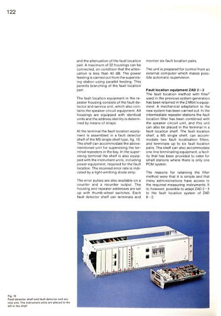
Fig. 16<br />
Fault detector shelf <strong>and</strong> fault detector <strong>and</strong> service<br />
unit. The instrument units are placed to the<br />
left in the shelf<br />
<strong>and</strong> the attenuation <strong>of</strong> the fault location<br />
pair. A maximum <strong>of</strong> 32 housings can be<br />
connected, on condition that the attenuation<br />
is less than 40 dB. The power<br />
feeding is carried out from the supervising<br />
station using parallel feeding. This<br />
permits branching <strong>of</strong> the fault location<br />
pair.<br />
The fault location equipment in the repeater<br />
housing consists <strong>of</strong> the fault detector<br />
<strong>and</strong> service unit, which also contains<br />
the speaker circuit equipment. All<br />
housings are equipped with identical<br />
units <strong>and</strong> the address identity is determined<br />
by means <strong>of</strong> straps.<br />
At the terminal the fault location equipment<br />
is assembled in a fault detector<br />
shelf <strong>of</strong> the M5 single shelf type, fig. 16.<br />
The shelf can accommodate the abovementioned<br />
unit <strong>for</strong> supervising the terminal<br />
repeaters in the bay. In the supervising<br />
terminal the shelf is also equipped<br />
with the instrument units, including<br />
power equipment, required <strong>for</strong> the fault<br />
location. The received error rate is indicated<br />
by a light-emitting diode strip.<br />
The error pulses are also available on a<br />
counter <strong>and</strong> a recorder output. The<br />
housing <strong>and</strong> repeater addresses are set<br />
up with thumb-wheel switches. Each<br />
fault detector shelf can terminate <strong>and</strong><br />
monitor six fault location pairs.<br />
The unit is prepared <strong>for</strong> control from an<br />
external computer which makes possible<br />
automatic supervision.<br />
Fault location equipment ZAD 2 — 3<br />
The fault location method with filter 2<br />
used in the previous system generation<br />
has been retained in the 2 Mbit/s equipment.<br />
A mechanical adaptation to the<br />
new system has been carried out. In the<br />
intermediate repeater stations the fault<br />
location filter has been combined with<br />
the speaker circuit unit, <strong>and</strong> this unit<br />
can also be placed in the terminal in a<br />
fault location shelf. The fault location<br />
shelf, a M5 single shelf, can accommodate<br />
two fault localisation filters,<br />
<strong>and</strong> terminate up to six fault location<br />
pairs. The shelf can also accommodate<br />
one line terminating equipment, a facility<br />
that has been provided to cater <strong>for</strong><br />
small stations where there is only one<br />
PCM system.<br />
The reasons <strong>for</strong> retaining the filter<br />
method were that it is simple <strong>and</strong> that<br />
many administrations have access to<br />
the required measuring instruments. It<br />
is, however, possible to adapt ZAD 2-3<br />
to the fault location system <strong>of</strong> ZAD<br />
8-2.


