2009_2 - Instituto Nacional de la Propiedad Industrial
2009_2 - Instituto Nacional de la Propiedad Industrial
2009_2 - Instituto Nacional de la Propiedad Industrial

You also want an ePaper? Increase the reach of your titles
YUMPU automatically turns print PDFs into web optimized ePapers that Google loves.
PATENTES CONCEDIDAS <strong>2009</strong><br />
ABRIL - JUNIO<br />
___________________________________________________________________________________<br />
al primer <strong>la</strong>do, teniendo también <strong>la</strong> abertura<br />
arrancadora una longitud; un primer elemento<br />
recolector dispuesto sobre el primer <strong>la</strong>do <strong>de</strong> <strong>la</strong><br />
abertura arrancadora y que gira alre<strong>de</strong>dor <strong>de</strong> un<br />
eje geométrico predominantemente vertical,<br />
estando el primer elemento recolector provisto<br />
con elementos portadores que están diseñados<br />
para agarrar <strong>la</strong>s p<strong>la</strong>ntas en pie a medida que el<br />
dispositivo recolector y arrancador está<br />
funcionando, así como para introducir <strong>la</strong>s p<strong>la</strong>ntas<br />
en <strong>la</strong> abertura arrancadora y para tras<strong>la</strong>dar <strong>la</strong>s<br />
p<strong>la</strong>ntas a través <strong>de</strong> al menos parte <strong>de</strong> longitud <strong>de</strong><br />
<strong>la</strong> abertura arrancadora; una unidad arrancadora<br />
que opera para llevar <strong>la</strong>s p<strong>la</strong>ntas en pie hacia<br />
abajo a través <strong>de</strong> <strong>la</strong> abertura arrancadora <strong>de</strong><br />
modo que <strong>la</strong>s partes útiles <strong>de</strong> <strong>la</strong>s p<strong>la</strong>ntas en pie<br />
son separadas <strong>de</strong> <strong>la</strong>s p<strong>la</strong>ntas por <strong>la</strong> p<strong>la</strong>ca<br />
arrancadora; y un segundo elemento recolector<br />
dispuesto sobre el segundo <strong>la</strong>do <strong>de</strong> <strong>la</strong> abertura<br />
arrancadora opuesto al primer elemento<br />
recolector, el segundo elemento recolector<br />
siendo también girado alre<strong>de</strong>dor <strong>de</strong> un segundo<br />
eje geométrico único predominantemente vertical<br />
y estando provistos con elementos portadores<br />
que están diseñados para agarrar <strong>la</strong>s p<strong>la</strong>ntas en<br />
pie, introducir <strong>la</strong>s p<strong>la</strong>ntas en <strong>la</strong> abertura<br />
arrancadora, y transportar <strong>la</strong>s p<strong>la</strong>ntas a través <strong>de</strong><br />
al menos parte <strong>de</strong> <strong>la</strong> longitud <strong>de</strong> <strong>la</strong> abertura<br />
arrancadora.<br />
Siguen 5 reivindicaciones.<br />
#8(71) Titu<strong>la</strong>r - MASCHINENFABRIK KEMPER GMBH<br />
& CO. KG<br />
AM BREUL, STADTLOHN 48703, DE<br />
#8(72) Inventor - KAPPELHOFF, HANS<br />
#8(74) Agente/s 736, 1075, 486<br />
-------------------------------------------------------<br />
<br />
#8(10) Patente <strong>de</strong> invención<br />
#8(11) Resolución N° AR033006B1<br />
#8(21) Acta N° P 20020101092<br />
#8(22) Fecha <strong>de</strong> Presentación 26/03/2002<br />
#8(24) Fecha <strong>de</strong> resolución 29/05/<strong>2009</strong><br />
#8(--) Fecha <strong>de</strong> vencimiento 26/03/2022<br />
#8(30) Prioridad convenio <strong>de</strong> Paris EP 01201232.4<br />
30/03/2001<br />
#8(51) Int. Cl. B60C 11/04<br />
#8(54) Titulo - UN NEUMATICO PARA UN<br />
AUTOMOTOR<br />
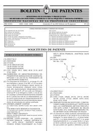
#8(57) Reivindicación 1: Neumático (1) para un<br />
automotor que tiene un p<strong>la</strong>no ecuatorial (7) y que<br />
compren<strong>de</strong> una radadura (2) y dos hombros (8,<br />
12; 412), comprendiendo dicha radadura (2) : -<br />
una primera y una segunda ranuras<br />
circunferenciales (3, 4; 5,4; 6, 5) ; - una primera y<br />
una segunda ranuras transversales (16, 18; 28,<br />
26; 38, 36; 216, 218 ; 236 ; 238) que forman al<br />
menos una hilera circunferencial (9, 10; 11; 209 ;<br />
211) <strong>de</strong> bloques ( 13 ; 14 ; 15 ; 213 ; 215)<br />
102<br />
ubicada entre dichas primera y segunda ranuras<br />
circunferenciales (3, 4 ; 5, 4 ; 6, 5); neumático (1),<br />
caracterizado porque cada uno <strong>de</strong> dichos<br />
bloques (13; 14 ; 15; 213 ; 215) está <strong>de</strong>limitado<br />
por una sección (103 ; 105 ; 106) <strong>de</strong> dicha<br />
primera ranura circunferencial (3 ; 5; 6) y por una<br />
primera y una segunda ranuras transversales<br />
(16, 18 ; 28, 26 ; 38, 36 ; 216, 218;236, 238) que<br />
se extien<strong>de</strong>n <strong>de</strong>s<strong>de</strong> dicha primera ranura<br />
circunferencial (3 ; 5 ; 6) y convergen en un<br />
vértice común (19 ; 29 ; 39 ; 219 ; 239) para<br />
formar un lóbulo espaciado <strong>de</strong> dicha segunda<br />
ranura circunferencial (4 ; 5 ), don<strong>de</strong> dicho vértice<br />
común ( 19 ; 29 ; 39 ; 219 ; 239) se encuentra<br />
separado <strong>de</strong> dicha segunda ranura<br />
circunferencial ( 4 ; 5) a través <strong>de</strong> una pestaña <strong>de</strong><br />
rodadura circunferencial continua (20, 24 ; 30),<br />
don<strong>de</strong> dicha segunda ranura transversal ( 18 ; 26<br />
; 218 ; 236) que <strong>de</strong>limita un bloque ( 13 ; 14 ; 15 ;<br />
213) se encuentra separada <strong>de</strong> una primera<br />
ranura transversal ( 16 ; 28 ; 38; 216 ; 238) que<br />
<strong>de</strong>limita un bloque inmediatamente posterior ( 13<br />
; 14 ; 15 ; 213 ; 215) por medio <strong>de</strong> una porción <strong>de</strong><br />
rodadura lisa ( 21 ; 25 ; 31 ; 221 ; 231) que se<br />
extien<strong>de</strong> <strong>de</strong>s<strong>de</strong> dicha primera ranura<br />
circunferencial ( 3 ; 5 ; 6) hasta dicha pestaña<br />
circunferencial ( 20 ; 24 ; 30),formando un solo<br />
cuerpo con dicha pestaña circunferencial y<br />
espaciado dicho bloque ( 13 ;14 ; 15; 213 ; 215) y<br />
el bloque inmediatamente posterior, entre sí .<br />
Siguen 18 reivindicaciones.<br />
#8(71) Titu<strong>la</strong>r - PIRELLI PNEUMATICI S.P.A.<br />
VIALE SARCA, 222, MILÁN 20126, IT<br />
#8(72) Inventor - COLOMBO, GIANFRANCO -<br />
CUCCO, GIANCARLO - BELLO, VITO<br />
#8(74) Agente/s 108<br />
-------------------------------------------------------<br />
<br />
#8(10) Patente <strong>de</strong> invención<br />
#8(11) Resolución N° AR023379B1<br />
#8(21) Acta N° P 20000101527<br />
#8(22) Fecha <strong>de</strong> Presentación 03/04/2000<br />
#8(24) Fecha <strong>de</strong> resolución 29/05/<strong>2009</strong><br />
#8(--) Fecha <strong>de</strong> vencimiento 03/04/2020<br />
#8(30) Prioridad convenio <strong>de</strong> Paris ES 99.00843<br />
23/04/1999<br />
#8(51) Int. Cl. F16L 41/04<br />
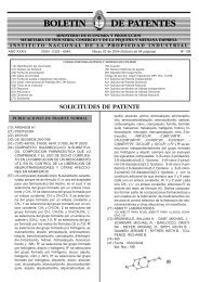
#8(54) Titulo - DISPOSITIVO PERFECCIONADO<br />
PARA LA REALIZACION DE DERIVACIONES<br />
EN UNA CONDUCCION DE FLUIDOS<br />
#8(57) Reivindicación 1: Dispositivo perfeccionado<br />
para <strong>la</strong> realización <strong>de</strong> <strong>de</strong>rivaciones en una<br />
conducción <strong>de</strong> fluidos, <strong>de</strong>l tipo que compren<strong>de</strong> un<br />
col<strong>la</strong>rín (8) y una abraza<strong>de</strong>ra flexible situada<br />
alre<strong>de</strong>dor <strong>de</strong> una conducción <strong>de</strong> red (11),<br />
presentando el col<strong>la</strong>rín (8) una junta tubu<strong>la</strong>r (9)<br />
cuya parte basal es apta para ajustar <strong>de</strong> forma<br />
estanca sobre <strong>la</strong> superficie <strong>de</strong> <strong>la</strong> conducción (11)