INSTALLATION INSTRUCTIONS
INSTALLATION INSTRUCTIONS
INSTALLATION INSTRUCTIONS

Create successful ePaper yourself
Turn your PDF publications into a flip-book with our unique Google optimized e-Paper software.
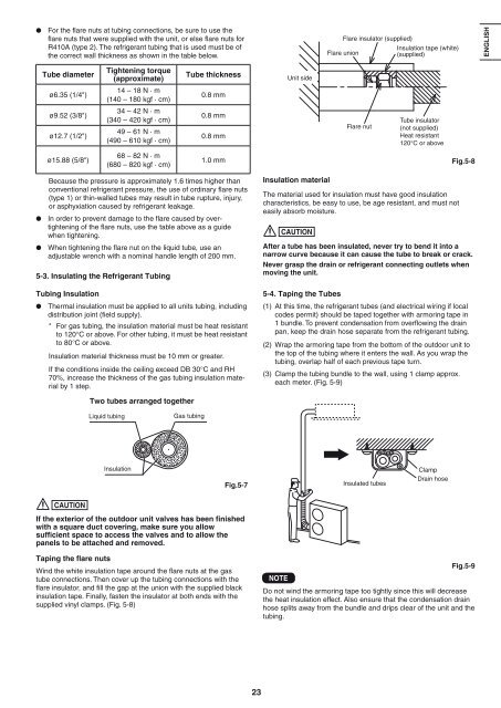
� For the fl are nuts at tubing connections, be sure to use the<br />
fl are nuts that were supplied with the unit, or else fl are nuts for<br />
R410A (type 2). The refrigerant tubing that is used must be of<br />
the correct wall thickness as shown in the table below.<br />
Tube diameter<br />
ø6.35 (1/4")<br />
ø9.52 (3/8")<br />
ø12.7 (1/2")<br />
ø15.88 (5/8")<br />
Tightening torque<br />
(approximate)<br />
14 – 18 N · m<br />
(140 – 180 kgf · cm)<br />
34 – 42 N · m<br />
(340 – 420 kgf · cm)<br />
49 – 61 N · m<br />
(490 – 610 kgf · cm)<br />
68 – 82 N · m<br />
(680 – 820 kgf · cm)<br />
Tube thickness<br />
0.8 mm<br />
0.8 mm<br />
0.8 mm<br />
Because the pressure is approximately 1.6 times higher than<br />
conventional refrigerant pressure, the use of ordinary fl are nuts<br />
(type 1) or thin-walled tubes may result in tube rupture, injury,<br />
or asphyxiation caused by refrigerant leakage.<br />
23<br />
Unit side<br />
Flare insulator (supplied)<br />
Flare union<br />
Flare nut<br />
Insulation tape (white)<br />
(supplied)<br />
Tube insulator<br />
(not supplied)<br />
Heat resistant<br />
120°C or above<br />
1.0 mm Fig.5-8<br />
Insulation material<br />
� In order to prevent damage to the fl are caused by overtightening<br />
of the fl are nuts, use the table above as a guide<br />
when tightening. CAUTION<br />
� When tightening the fl are nut on the liquid tube, use an<br />
adjustable wrench with a nominal handle length of 200 mm.<br />
5-3. Insulating the Refrigerant Tubing<br />
Tubing Insulation 5-4. Taping the Tubes<br />
� Thermal insulation must be applied to all units tubing, including<br />
distribution joint (fi eld supply).<br />
* For gas tubing, the insulation material must be heat resistant<br />
to 120°C or above. For other tubing, it must be heat resistant<br />
The material used for insulation must have good insulation<br />
characteristics, be easy to use, be age resistant, and must not<br />
easily absorb moisture.<br />
After a tube has been insulated, never try to bend it into a<br />
narrow curve because it can cause the tube to break or crack.<br />
Never grasp the drain or refrigerant connecting outlets when<br />
moving the unit.<br />
(1) At this time, the refrigerant tubes (and electrical wiring if local<br />
codes permit) should be taped together with armoring tape in<br />
1 bundle. To prevent condensation from overfl owing the drain<br />
pan, keep the drain hose separate from the refrigerant tubing.<br />
to 80°C or above. (2) Wrap the armoring tape from the bottom of the outdoor unit to<br />
Insulation material thickness must be 10 mm or greater.<br />
If the conditions inside the ceiling exceed DB 30°C and RH<br />
70%, increase the thickness of the gas tubing insulation material<br />
by 1 step.<br />
CAUTION<br />
Two tubes arranged together<br />
Liquid tubing Gas tubing<br />
Insulation<br />
Fig.5-7<br />
If the exterior of the outdoor unit valves has been finished<br />
with a square duct covering, make sure you allow<br />
sufficient space to access the valves and to allow the<br />
panels to be attached and removed.<br />
Taping the �are nuts<br />
Wind the white insulation tape around the fl are nuts at the gas<br />
tube connections. Then cover up the tubing connections with the<br />
fl are insulator, and fi ll the gap at the union with the supplied black<br />
insulation tape. Finally, fasten the insulator at both ends with the<br />
supplied vinyl clamps. (Fig. 5-8)<br />
the top of the tubing where it enters the wall. As you wrap the<br />
tubing, overlap half of each previous tape turn.<br />
(3) Clamp the tubing bundle to the wall, using 1 clamp approx.<br />
each meter. (Fig. 5-9)<br />
NOTE<br />
Insulated tubes<br />
Clamp<br />
Drain hose<br />
Fig.5-9<br />
Do not wind the armoring tape too tightly since this will decrease<br />
the heat insulation effect. Also ensure that the condensation drain<br />
hose splits away from the bundle and drips clear of the unit and the<br />
tubing.<br />
ENGLISH<br />
��������� E������� PORTUGUÊS<br />
�������<br />
����������