MASCHIO GASPARDO S.p.A. - Opico
MASCHIO GASPARDO S.p.A. - Opico
MASCHIO GASPARDO S.p.A. - Opico

Create successful ePaper yourself
Turn your PDF publications into a flip-book with our unique Google optimized e-Paper software.
ITALIANO<br />
3.3 PRIMA DELL'USO<br />
Prima di mettere in funzione la macchina,<br />
eseguire le seguenti operazioni:<br />
- Controllare che la macchina sia perfettamente<br />
in ordine, che i lubrificanti<br />
siano al giusto livello (vedere capitolo<br />
«Manutenzione») e che tutti gli organi<br />
soggetti ad usura e deterioramento siano<br />
pienamente efficienti.<br />
- Controllare che la macchina, anche<br />
quella provvista di rullo, sia ben regolata<br />
per l'ottenimento della profondità<br />
di lavoro desiderata.<br />
AVVERTENZA<br />
Verificare, prima della messa in funzione<br />
della macchina, che le protezioni<br />
antinfortunistiche fornite smontate<br />
per ragioni di trasporto, siano state<br />
correttamente installate.<br />
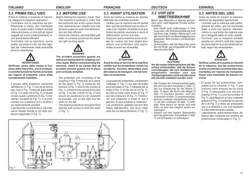
- Il gruppo delle protezioni, composto<br />
dall'attacco (1 Fig. 7) che fà da fermo<br />
per i tubi (2 Fig. 7) bloccati dalla staffa<br />
(3 Fig. 7) e dalle viti (4 Fig. 7), è fissato<br />
al tubo quadro anteriore (5 Fig. 7) mediante<br />
i cavallotti (6 Fig. 7), e va posizionato<br />
uno a destra e uno a sinistra il<br />
più esternamente possibili.<br />
- Lateralmente, su entrambe le fiancate,<br />
vanno fissate tramite le viti delle protezioni<br />
sagomate (7 Fig. 7).<br />
ENGLISH FRANÇAIS DEUTSCH<br />
ESPAÑOL<br />
3.3 BEFORE USE<br />
Before starting the machine, check that:<br />
- The machine is perfectly in order, that<br />
the lubricants are at the correct levels<br />
(see «Maintenance» chapter) and that<br />
all parts subject to wear and deterioration<br />
are fully efficient.<br />
- Check the machine, also thet fitted with<br />
roller, is correctly positioned for obtain<br />
the rigth working depth.<br />
WARNING<br />
The accident prevention guards are<br />
delivered dismantled for shipping volume<br />
needs. Before commissioning the<br />
machine, check to be certain that all<br />
accident prevent guards are in place<br />
and correctly installed.<br />
- The protection unit, consisting of the<br />
coupling (1 Fig. 7) that acts as a clamp<br />
for the pipes (2 Fig. 7) locked by the<br />
bracket (3 Fig. 7) and by the screws (4<br />
Fig. 7), is fixed to the square front pipe<br />
(5 Fig. 7) by the U-bolts (6 Fig. 7) and<br />
should be positioned as far outwards<br />
as possible, one on the right and the<br />
other on the left.<br />
- The shaped protections should be fixed<br />
laterally with screws to both the sides<br />
(7 Fig. 7).<br />
3.3 AVANT UTILISATION<br />
Avant de mettre la machine en marche<br />
effectuez les contrôles suivants:<br />
- Vérifiez que la machine est en parfait<br />
état, que les lubrifiants sont au bon niveau<br />
(voir chapitre «Entretien») et que<br />
toutes les pièces soumises à usure et<br />
détérioration sont en bon état.<br />
- S'assurer que la machine aussi ce dotée<br />
de rouleau est bien réglée pour<br />
obtenir une profondeur plus appropriées<br />
suivant les nécessités.<br />
ATTENTION<br />
Avant la mise en service de la machine<br />
vérifier que les protections contre les<br />
accidents, fournies démontées pour<br />
des raisons de transport, ont été montées<br />
correctement.<br />
- Le groupe des protections, comprenant<br />
l’attelage (1 Fig. 7) qui sert de butée<br />
pour les tubes (2 Fig. 7) bloqués par la<br />
bride (3 Fig. 7) et par les vis (4 Fig. 7),<br />
est fixé au tube carré avant (5 Fig. 7)<br />
par des crampons (6 Fig. 7). Positionner<br />
une protection à droite et une à<br />
gauche, le plus possible à l’extérieur.<br />
- Les protections galbées doivent être<br />
fixées latéralement, des deux côtés<br />
avec les vis des protections (7 Fig. 7).<br />
3.3 VOR DER<br />
INBETRIEBNAHME<br />
Bevor das Maschine in Betrieb genommen<br />
wird, sind folgende Punkte sicherzustellen:<br />
- Das Gerät muß vollkommen in Ordnung<br />
sein, die Schmierstoffüllung muß<br />
stimmen (vgl. Kapitel «Wartung») und<br />
alle Verschleiß und Beschädigung ausgesetzten<br />
Teile müssen voll leistungsfähig<br />
sein.<br />
- Sicherstellen, daß die Maschine, auch<br />
die mit Rolle, gut eingestellt ist für die<br />
Gewünschte tiefe.<br />
ACHTUNG<br />
Vor der ersten Inbetriebnahme der Maschine<br />
sicherstellen, daß die Schutzvorrichtungen,<br />
die zum Umfallschutz<br />
mitgeliefert werden und aus<br />
Transportgründen nicht montiert sind,<br />
alle korrekt installiert worden sind.<br />
- Die Gruppe der Schutzvorrichtungen,<br />
die sich aus dem Anschluß (1 Abb. 7),<br />
der zur Arretierung für die Rohre (2<br />
Abb. 7) dient, die durch den Bügel (3<br />
Abb. 7) blockiert werden, und den<br />
Schrauben (4 Abb. 7) zusammensetzt,<br />
wird am vorderen Vierkantrohr (5 Abb.<br />
7) mit den U-Bolzen (6 Abb. 7) befestigt.<br />
Eine davon ist rechts und eine<br />
links, so weit wie möglich außen anzubringen.<br />
- Seitlich auf den beiden Seitenteilen<br />
sind die geformten Schutzteile (7 Abb.<br />
7) mit Schrauben zu befestigen.<br />
3.3 ANTES DEL USO<br />
Antes de poner en función la máquina,<br />
efectuar las siguientes operaciones:<br />
- Controlar que la máquina esté perfectamente<br />
en orden, que los lubricantes<br />
estén a nivel (ver capítulo «Mantenimiento»)<br />
y que todos los organos sujetos<br />
a desgaste estén en buen estado.<br />
- Controlar que la máquina también<br />
aquella con cilindro, esté bien regulada<br />
para obtener la profundidad de trabajo<br />
según las necesidades.<br />
ATENCION<br />
Verificar, antes de la puesta en función<br />
de la máquina, que las protecciones<br />
contra accidentes suministradas desmontadas<br />
por razones de transporte,<br />
hayan sido instaladas de manera correcta.<br />
- El grupo de las protecciones, compuesto<br />
por la conexión (1 Fig. 7) que<br />
funciona como bloqueo de los tubos<br />
(2 Fig. 7) bloqueados a su vez por el<br />
soporte (3 Fig. 7) y por los tornillos (4<br />
Fig. 7), está fijado en el tubo cuadrado<br />
anterior (5 Fig. 7) mediante los pernos<br />
de U (6 Fig. 7) y debe ser emplazado<br />
uno a la derecha y uno a la izquierda<br />
lo más externamente posible.<br />
- Lateralmente, sobre ambos lados, debemos<br />
fijar mediante los tornillos las<br />
protecciones molduradas (7 Fig. 7).<br />
7<br />
6 5<br />
5 6<br />
7<br />
1<br />
4<br />
4<br />
1<br />
Fig. 7<br />
3<br />
2<br />
2<br />
3<br />
21