MASCHIO GASPARDO S.p.A. - Opico
MASCHIO GASPARDO S.p.A. - Opico
MASCHIO GASPARDO S.p.A. - Opico

You also want an ePaper? Increase the reach of your titles
YUMPU automatically turns print PDFs into web optimized ePapers that Google loves.
ITALIANO<br />
ENGLISH FRANÇAIS DEUTSCH<br />
ESPAÑOL<br />
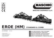
ATTENZIONE<br />
Le piastre (1 Fig. 8) vanno montate<br />
sempre e solo come mostrato in Fig.<br />
8 con i fori posizionati anteriormente<br />
al tubo quadro.<br />
La ditta costruttrice declina ogni responsabilità<br />
per rotture sulla macchina<br />
o sul trattore conseguenti al mancato<br />
rispetto di questa indicazione.<br />
IMPORTANT<br />
The plates (1 Fig. 8) must always and<br />
only be mounted as shown in Fig. 8<br />
with the holes towards the front of the<br />
square tubular.<br />
The Manufacturer declines any liability<br />
for damage to the machine or the<br />
tractor if this essential installation requirement<br />
is not observed.<br />
ATTENTION<br />
Les plaques (1 Fig. 8) doivent obligatoirement<br />
être montées comme illustré<br />
dans la Fig. 8 en utilisant les trous<br />
placés à l’avant du tube carré.<br />
Le constructeur décline toute responsabilité<br />
pour les ruptures sur la machine<br />
ou sur le tracteur dérivant de<br />
l’inobservation de cette prescription.<br />
ACHTUNG<br />
Die Platten (1 Abb. 8) dürfen nur und<br />
ausschließlich so montiert werden,<br />
wie es in Abb. 8 gezeigt ist, nämlich<br />
mit den Bohrungen, die vor dem<br />
Vierkantrohr angeordnet sind. Der<br />
Hersteller haftet nicht für die Beschädigung<br />
der Maschine oder des Schleppers<br />
infolge der Nichtbeachtung dieser<br />
Angabe.<br />
ATENCION<br />
Las placas (1 Fig. 8) deben ser montadas<br />
siempre y solamente según lo<br />
indicado en la Fig. 8 con los orificios<br />
posicionados delante del tubo cuadrado.<br />
La firma constructora no es responsable<br />
de rupturas en la máquina o<br />
en el tractor originadas por falta de<br />
respeto de esta indicación.<br />
PERICOLO<br />
L'applicazione al trattore è una fase<br />
molto pericolosa. Fare molta attenzione<br />
effettuare l'intera operazione seguendo<br />
le istruzioni.<br />
La corretta posizione trattore/macchina,<br />
viene determinata, ponendo la macchina<br />
ad una distanza, dal trattore, tale che<br />
il giunto cardanico resti esteso 5-10 cm<br />
dalla posizione di massima chiusura.<br />
A questo punto, procedere come segue:<br />
1) Accostare le parallele del sollevatore<br />
ponendole all'interno delle piastre (1<br />
Fig. 8), inserire il perno (2 Fig. 8) nel<br />
foro predisposto e bloccare con le<br />
copiglie a scatto.<br />
2) Bloccare le parallele del sollevatore<br />
con le apposite catene e tenditori paralleli<br />
sul trattore. Tale accorgimento<br />
deve essere messo in atto per evitare<br />
qualsiasi spostamento, in senso orizzontale,<br />
della macchina.<br />
3) Innestare l'albero cardanico e assicurarsi<br />
che sia perfettamente bloccato<br />
sulla presa di forza. Verificare che la<br />
protezione ruoti liberamente e fissarla<br />
con l'apposita catenella.<br />
Rimuovere il sostegno dall'albero cardanico<br />
(2 Fig. 3) e riporlo fissandolo<br />
nell'apposito aggancio.<br />
4) Collegare il terzo punto superiore ed<br />
effettuare una corretta regolazione<br />
con il tirante (1 Fig. 9) verificando che<br />
il piano superiore della macchina (A<br />
Fig. 9) risulti parallelo al piano terra<br />
(B Fig. 9).<br />
DANGER<br />
Application of any implement to a tractor<br />
is a very dangerous operation and<br />
must only be carried out with the utmost<br />
care in compliance with the instructions.<br />
The correct tractor/machine position is<br />
established by setting the implement at<br />
such a distance from the tractor that the<br />
universal coupling remains 5-10 cm from<br />
its maximum closing position. Now proceed<br />
in the following way:<br />
1) Near the lift bars, setting them in the<br />
most suitable plates (1 Fig. 8). Insert<br />
the pin (2 Fig. 8) into the relative hole<br />
and lock in place with the snap-in split<br />
pins.<br />
2) Lock the lift links using the relative<br />
chains and couplings parallel to the<br />
tractor.<br />
This operation must be carried out to<br />
prevent the machine from moving in<br />
a horizontal direction.<br />
3) Engage the cardan shaft and check<br />
that it is perfectly locked on the pto.<br />
Check that the guard is free to turn<br />
and fix it with the relative latch.<br />
Remove the cardan shaft support (2<br />
Fig. 3) and re-position it by fixing it on<br />
the relative hook.<br />
4) Connect the upper third-point and correctly<br />
regulate by means of the adjuster<br />
(1 Fig. 9), checking that the upper<br />
surface of the machine (A Fig. 9)<br />
is parallel to the ground (B Fig. 9).<br />
DANGER<br />
L’attelage au tracteur est une opération<br />
très dangereuse.<br />
Faites très attention et respectez les<br />
instructions.<br />
La position exacte de tracteur/machine<br />
est obtenue en mettant l’appareil à une<br />
distance telle que le joint de cardan reste<br />
détendu de 5-10 cm par rapport à la position<br />
de fermeture totale. Après quoi procédez<br />
de la manière suivante:<br />
1) Approchez les barres du relevage en<br />
les plaçant à l’intérieur des plaques<br />
les plus appropriées (1 Fig. 8), introduisez<br />
l’axe (2 Fig. 8) dans le trou<br />
correspondant et bloquez par les goupilles<br />
à encastrement.<br />
2) Bloquez les barres du relevage avec<br />
les chaînes et les tendeurs parallèles<br />
sur le tracteur. Cette opération a pour<br />
but d’éviter tout débattement de la<br />
machine dans le sens horizontal.<br />
3) Engagez l’arbre à cardans dans la<br />
prise de force et contrôlez qu’il est bloqué<br />
parfaitement. Vérifiez que la protection<br />
tourne librement et fixez-la par<br />
la chaînette.<br />
Enlevez le support de l'arbre à cardans<br />
(2 Fig. 3) et rangez-le en le fixant<br />
dans le crochet spécial.<br />
4) Reliez le troisième point supérieur et<br />
réglez correctement à l’aide du tirant<br />
(1 Fig. 9).<br />
Assurez-vous que le plan supérieur de<br />
la machine (A Fig. 9) soit pratiquement<br />
parallèle au terrain (B Fig. 9).<br />
GEFAHR<br />
Der Anbau am Schlepper ist ein sehr<br />
gefährlicher Schritt. Sehr vorsichtig<br />
vorgehen und den ganzen Vorgang<br />
gemäß der Anweisung ausführen.<br />
Die korrekte Position von Schlepper und<br />
Maschine wird dadurch festgelegt, daß<br />
man das Maschine in so einem Abstand<br />
vor den Schlepper bringt, daß die Gelenkwelle<br />
5-10 cm länger ist als bei der Position,<br />
in der sie so weit wie möglich geschlossen<br />
ist. Nun folgendermaßen vorgehen:<br />
1) Die Lenker des Krafthebers annähern<br />
und in die am besten geeigneten Platten<br />
schieben (1 Abb. 8). Den Bolzen<br />
(2 Abb.8) in das Loch stecken und mit<br />
dem einrastenden Splint blockieren.<br />
2) Die Lenker des Krafthebers mit den<br />
Stabilisierungsketten und Spannvorrichtungen<br />
des Schleppers parallel<br />
zum Schlepper blockieren.<br />
Dieser Vorgang ist auch bei Straßenfahrten<br />
erforderlich, damit das Maschine<br />
nicht seitlich ausschwenkt.<br />
3) Die Gelenkwelle einstecken und sicherstellen,<br />
daß sie fest mit der Zapfwelle<br />
verbunden ist. Sicherstellen,<br />
daß der Gelenkwellenschutz sich frei<br />
versrehen kann und mit der Kette befestigen.<br />
Den Halter der Gelenkwelle<br />
(2 Fig. 3) entfernen und ihn in dem<br />
vorgesehenen Haken befestigen.<br />
4) Den oberen Kupplungspunkt anschließen<br />
und den oberen Lenker (1 Abb.<br />
9) korrekt einstellen. Sicherstellen,<br />
daß die obere Haubenkante der Maschine<br />
(A Abb. 9) parallel zum Boden<br />
(B Abb. 9) steht.<br />
PELIGRO<br />
La aplicación al tractor es una fase<br />
muy peligrosa. Prestar mucha atención<br />
y efectuar to da la operación siguiendo<br />
las instrucciones.<br />
La correcta posición tractor/máquina, se<br />
determina, colocando el equipo a una distancia<br />
del tractor, en modo tal que la junta<br />
cardánica se extienda 5-10 cm desde<br />
la posición de máximo cierre. En este momento:<br />
1) Acercar las barras del elevador<br />
poníendolas dentro de las placas más<br />
indicadas (1 Fig. 8), introducir el perno<br />
(2 Fig. 8) en el orificio y bloquear<br />
con los pasadores de resorte.<br />
2) Bloquear las barras del elevador con<br />
las respectivas cadenas y tensores<br />
paralelos en el tractor.<br />
Dicha operación es necesaria para<br />
evitar todo tipo de desplazamiento,<br />
en sentido horizontal, de la máquina.<br />
3) Acoplar el árbol cardánico y controlar<br />
que quede bien bloqueado en la toma<br />
de fuerza.<br />
Verificar que la protección gire libremente<br />
y fijarla con la relativa cadena.<br />
Extraer el soporte de árbol cardánico<br />
(2 Fig. 3) y volver a colocarlo fijándolo<br />
con el correspondiente gancho.<br />
4) Conectar el tercer punto superior y<br />
efectuar una correcta regulación con<br />
el tirante de regulación (1 Fig. 9) controlando<br />
que el plano superior de la<br />
máquina (A Fig. 9) resulte paralelo al<br />
plano al nivel del suelo (B Fig. 9).<br />
23