GIRAFFETTA OK15.pmd - Opico
GIRAFFETTA OK15.pmd - Opico
GIRAFFETTA OK15.pmd - Opico

Create successful ePaper yourself
Turn your PDF publications into a flip-book with our unique Google optimized e-Paper software.
ITALIANO ENGLISH FRANÇAIS DEUTSCH<br />
ESPAÑOL<br />
3) Innestare l'albero cardanico e assicurarsi<br />
che sia perfettamente bloccato<br />
sulla presa di forza.<br />
Verificare che la protezione ruoti liberamente<br />
e fissarla con l'apposita<br />
catenella. Rimuovere il sostegno dall'albero<br />
cardanico.<br />
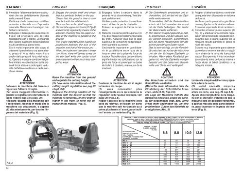
4) Collegare il terzo punto superiore (C<br />
Fig.8) ed effettuare una corretta<br />
regolazione con il tirante, verificando<br />
che il piano superiore della macchina<br />
risulti parallelo al piano terra.<br />
Ciò è molto importante allo scopo di<br />
ottenere il parallelismo tra asse albero<br />
presa di forza della macchina e<br />
quello della presa di forza del trattore.<br />
Operare in queste condizioni significa<br />
limitare le sollecitazioni sulla presa<br />
di forza stessa e prolungare la durata<br />
dell'albero cardanico e della macchina<br />
stessa.<br />
ATTENZIONE<br />
Sollevare la macchina dal terreno e<br />
registrare l'altezza di taglio.<br />
(Per avere maggiori informazioni riguardo<br />
la registrazione dell’altezza di<br />
taglio vedere cap. 3.8 a pag. 29).<br />
Regolare l'assetto della macchina con<br />
il sollevatore, facendo in modo che la<br />
macchina sia orizzontale, o appena<br />
più alta anteriormente, per favorire l'ingresso<br />
del materiale (Fig. 9).<br />
3) Engage the cardan shaft and check<br />
that it is perfectly locked on the pto.<br />
Check that the guard is free to turn<br />
and fix it with the relative latch.<br />
Remove the cardan shaft support.<br />
4) Connect the upper third-point (C Fig.8)<br />
and correctly regulate by means of the<br />
adjuster, checking that the upper surface<br />
of the machine is parallel to the<br />
ground.<br />
This is very important since it achieves<br />
parallelism between the axis of the<br />
machine and that of the tractor pto.<br />
When the implement operates in these<br />
conditions, there will be less stress on<br />
the pto itself while the cardan shaft<br />
and implement will be much less subject<br />
to wear.<br />
ATTENTION<br />
Raise the machine from the ground<br />
and regulate the cutting height.<br />
(To have more information about the<br />
cutting height regulation see pag.29<br />
chapt. 3.8).<br />
Regulate the driving position of the<br />
machine with the hoister so that the<br />
machine is horizontal, or only slightly<br />
higher in the front, to favor the entrance<br />
of the material (Fig. 9).<br />
3) Engagez l’arbre à cardans dans la<br />
prise de force et contrôlez qu’il est bloqué<br />
parfaitement.<br />
Vérifiez que la protection tourne librement<br />
et fixez-la par la chaînette.<br />
Enlevez le support de l’arbre à cardans.<br />
4) Reliez le troisième point supérieur (C<br />
Fig. 8) et réglez correctement à l’aide<br />
du tirant. Assurez-vous que le plan<br />
supérieur de la machine soit pratiquement<br />
parallèle au terrain.<br />
Ceci est très important en vue d’obtenir<br />
le parallélisme entre l’axe de la<br />
houe et celui de la prise de force du<br />
tracteur. Travailler dans ces conditions<br />
signifie limiter les sollicitations sur la<br />
prise de force et prolonger la durée<br />
de l’arbre à cardans, mais aussi de la<br />
machine.<br />
ATTENTION<br />
Soulever la machine du sol et régler<br />
la hauteur de coupe.<br />
(Si vous nécessitez plus<br />
renseignments en ce qui concerne la<br />
régulation de la hauteur de coupe, voir<br />
page 29 chap.3.8).<br />
Régler l’assiette de la machine avec<br />
celle du releveur, en faisant en sorte<br />
que la machine soit horizontale ou à<br />
peine plus haute à l’avant, pour faciliter<br />
l’entrée du matériau (Fig. 9).<br />
3) Die Gelenkwelle einstecken und sicherstellen,<br />
daß sie fest mit der Zapfwelle<br />
verbunden ist.<br />
Sicherstellen, daß der Gelenkwellenschutz<br />
sich frei versrehen kann und<br />
mit der Kette befestigen. Den Halter<br />
der Gelenkwelle entfernen.<br />
4) Den oberen Kupplungspunkt (C Abb.<br />
8) anschließen und den oberen Lenker<br />
korrekt einstellen. Sicherstellen,<br />
daß die obere Haubenkante der Maschine<br />
parallel zum Boden steht.<br />
Das ist sehr wichtig, um die Parallelität<br />
zwischen der Achse der Maschine<br />
und der der Schlepper-Zapfwelle zu<br />
erhalten. Wenn diese Parallelität gegeben<br />
ist, wird die Zapfwelle weniger<br />
belastet und das Leben von Gelenkwelle<br />
und Gerät wird verlängert.<br />
ACHTUNG<br />
Die Maschine anheben und die<br />
Schnitthöhe einstellen.<br />
(Wenn Sie mehr Information über die<br />
Einstellung der Schnitthöhe brauchen,<br />
siehe S.29, Kap.3.8).<br />
Die Lage der Maschine mithilfe des<br />
Hubwerks einstellen, sodaß sie parallel<br />
zur Bodenfläche liegt, bzw. vorne<br />
etwas mehr angehoben ist, um eine<br />
problemlose Zufuhr des Materials zu<br />
ermöglichen (Abb. 9).<br />
3) Acoplar el árbol cardánico y controlar<br />
que quede bien bloqueado en la toma<br />
de fuerza.<br />
Verificar que la protección gire libremente<br />
y fijarla con la relativa cadena.<br />
Extraer el soporte de árbol cardánico.<br />
4) Conectar el tercer punto superior (C<br />
Fig. 8) y efectuar una correcta regulación<br />
con el tirante de regulación controlando<br />
que el plano superior de la<br />
máquina resulte paralelo al plano al<br />
nivel del suelo.<br />
Esto es muy importante para obtener<br />
parelelismo entre el eje de la máquina<br />
y el eje de la toma de fuerza del<br />
tractor. Esto permite limitar los esfuerzos<br />
sobre la toma de fuerza misma y<br />
hacer durar el árbol cardánico y la<br />
máquina misma.<br />
ATENCIÓN<br />
Levante la máquina del terreno y ajuste<br />
la altura de corte.<br />
(Si usted necesita mayores<br />
informaciónes sobre el ajuste de la<br />
altura de corte, vea pag. 29 cap.3.8).<br />
Ajuste el eje longitudinal de la máquina<br />
con el elevador, tratando de que la<br />
máquina esté en posición horizontal,<br />
o apenas más alta en la parte delantera,<br />
para favorecer el ingreso del material<br />
(Fig. 9).<br />
C<br />
TABELLA COPPIE DI SERRAGGIO VITI (valori espressi in Nm) - CHART: SCREW TIGHTENING TORQUES<br />
(settings given in Nm) - TABLEAU COUPLES DE SERRAGE DES VIS (valeurs exprimées en Nm)<br />
TABELLE DER ANZUGSMOMENTE DER SCHRAUBEN (Werte in Nm ausgedrückt)<br />
- TABLAS PARES DE TORSION TORNILLOS (valores expresados en Nm)<br />
Fig. 8<br />
A<br />
B<br />
CLASSE - CLASS<br />
CLASSE - KLASSE-<br />
CLASE<br />
VITE PASSO FINE<br />
FINE PITCH SCREWS 6.6 8.8 10.9 12.9<br />
VIS A PAS FIN<br />
SCHRAUBE STEIGUNG FEIN<br />
TORNILLO PASO FIN<br />
M8 x 1 15 26 36 44<br />
M10 x 1.25 30 52 74 88<br />
M12 x 1.25 51 91 127 153<br />
M14 x 1.5 81 143 201 241<br />
M16 x 1.5 120 214 301 361<br />
M18 x 1.5 173 308 433 520<br />
M20 x 1.5 242 431 606 727<br />
M22 x 1.5 321 571 803 964<br />
M24 x 2 411 731 1028 1234<br />
M27 x 2 601 1070 1504 1806<br />
M30 x 2 832 1480 2081 2498<br />
24