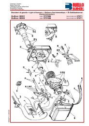
Bruciatori di gasolio Öl-Gebläsebrenner Brûleurs fioul Oil burners
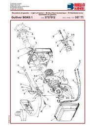
Bruciatori di gasolio Öl-Gebläsebrenner Brûleurs fioul Oil burners
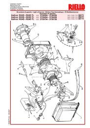
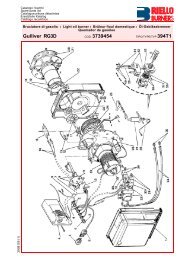
Bruciatori di gasolio Öl-Gebläsebrenner Brûleurs fioul Oil burners

You also want an ePaper? Increase the reach of your titles
YUMPU automatically turns print PDFs into web optimized ePapers that Google loves.
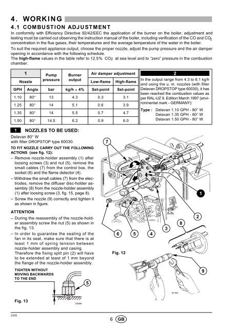
4. WORKING4.1 COMBUSTION ADJUSTMENTIn conformity with Efficiency Directive 92/42/EEC the application of the burner on the boiler, adjustment andtesting must be carried out observing the instruction manual of the boiler, inclu<strong>di</strong>ng verification of the CO and CO 2concentration in the flue gases, their temperatures and the average temperature of the water in the boiler.To suit the required appliance output, choose the proper nozzle, adjust the pump pressure and the air damper4opening in accordance with the following schedule.The high-flame values in the table refer to 12.5% CO2 at sea level and to “zero” pressure in the combustionchamber.1 Pump Burner Air damper adjustmentNozzlepressure outputLow-flame High-flameGPH Angle bar kg/h ± 4% Set-point Set-point1.10 80° 13 4.3 0.3 3.11.25 80° 14 5.1 0.6 3.91.35 80° 14 5.5 0.7 4.71.50 80° 14.5 6.2 0.9 6.02In the output range from 4.3 to 6.1 kg/hand using the u. m. nozzles (with filterDelavan DROPSTOP type 60030), it hasbeen reached the combustion values asper RAL-UZ 9, E<strong>di</strong>tion March 1997 (environmentalmark - GERMANY):Type : Delavan 1.10 GPH - 80° WDelavan 1.35 GPH - 80° WDelavan 1.50 GPH - 80° W1NOZZLES TO BE USED:Delavan 80° Wwith filter DROPSTOP type 60030.TO FIT NOZZLE CARRY OUT THE FOLLOWINGACTIONS (see fig. 12):– Remove nozzle-holder assembly (1) afterloosing screws (3) and nut (5), remove thesmall cables (7) from the control box, thesocket (6) and the flame detector (4).– Withdraw the small cables (7) from the electrodes,remove the <strong>di</strong>ffuser <strong>di</strong>sc-holder assembly(8) from the nozzle-holder assembly(1) after loosing screw (3, fig. 15, page 8).– Screw the nozzle (9) correctly and tighten itas shown in figure.71ATTENTION– During the reassembly of the nozzle-holderassembly screw the nut (5) as shown inthe fig. 13.– In order to guarantee the sealing of thefan in its seat, make sure that there is atleast 1 mm of spring tension betweennozzle-holder assembly and casing.Therefore the fixing split pin (2) will haveto be extended at least of 1 mm beyondthe flange of the nozzle-holder assembly.6 5 4Fig. 12382TIGHTEN WITHOUTMOVING BACKWARDSTO THE END59S7160Fig. 13D568423206 GB