Istruzioni di posa Workbook - OWA
Istruzioni di posa Workbook - OWA
Istruzioni di posa Workbook - OWA

Create successful ePaper yourself
Turn your PDF publications into a flip-book with our unique Google optimized e-Paper software.
Installazione <strong>di</strong> sistemi <strong>OWA</strong>construct ®<br />
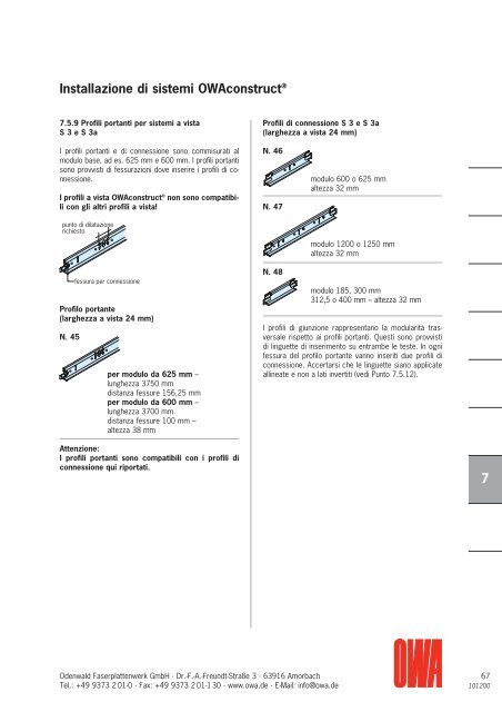
7.5.9 Profili portanti per sistemi a vista<br />
S 3 e S 3a<br />
I profili portanti e <strong>di</strong> connessione sono commisurati al<br />
modulo base, ad es. 625 mm e 600 mm. I profili portanti<br />
sono provvisti <strong>di</strong> fessurazioni dove inserire i profili <strong>di</strong> co -<br />
nnessione.<br />
I profili a vista <strong>OWA</strong>construct ® non sono compatibili<br />
con gli altri profili a vista!<br />
punto <strong>di</strong> <strong>di</strong>latazione<br />
richiesto<br />
fessura per connessione<br />
Profilo portante<br />
(larghezza a vista 24 mm)<br />
N. 45<br />
per modulo da 625 mm –<br />
lunghezza 3750 mm<br />
<strong>di</strong>stanza fessure 156,25 mm<br />
per modulo da 600 mm –<br />
lunghezza 3700 mm<br />
<strong>di</strong>stanza fessure 100 mm –<br />
altezza 38 mm<br />
Attenzione:<br />
I profili portanti sono compatibili con i profili <strong>di</strong><br />
connessione qui riportati.<br />
Odenwald Faserplattenwerk GmbH · Dr.-F.-A.-Freundt-Straße 3 · 63916 Amorbach<br />
Tel.: +49 9373 2 01-0 · Fax: +49 9373 2 01-130 · www.owa.de · E-Mail: info@owa.de<br />
G<br />
Profili <strong>di</strong> connessione S 3 e S 3a<br />
(larghezza a vista 24 mm)<br />
N. 46<br />
N. 47<br />
N. 48<br />
modulo 600 o 625 mm<br />
altezza 32 mm<br />
modulo 1200 o 1250 mm<br />
altezza 32 mm<br />
modulo 185, 300 mm<br />
312,5 o 400 mm – altezza 32 mm<br />
I profili <strong>di</strong> giunzione rappresentano la modularità tras -<br />
versale rispetto ai profili portanti. Questi sono provvisti<br />
<strong>di</strong> linguette <strong>di</strong> inserimento su entrambe le teste. In ogni<br />
fessura del profilo portante vanno inseriti due profili <strong>di</strong><br />
connessione. Accertarsi che le linguette siano applicate<br />
allineate e non a lati invertiti (ve<strong>di</strong> Punto 7.5.12).<br />
1<br />
1<br />
1<br />
1<br />
1<br />
1<br />
7<br />
1<br />
67<br />
101200
![OWAtecta ® Preisliste 1/2013 - Druckschrift 300 [PDF, 5607 KB]](https://img.yumpu.com/22678096/1/184x260/owatecta-r-preisliste-1-2013-druckschrift-300-pdf-5607-kb.jpg?quality=85)
![Schallabsorption [PDF, 1131 KB] - OWA](https://img.yumpu.com/22510790/1/184x260/schallabsorption-pdf-1131-kb-owa.jpg?quality=85)
![S 7 – OWAplan [PDF, 452 KB]](https://img.yumpu.com/22270280/1/184x260/s-7-owaplan-pdf-452-kb.jpg?quality=85)
![11 OWAtecta ® Metalldecken – DS 900 [PDF, 939 KB]](https://img.yumpu.com/21890962/1/184x260/11-owatecta-r-metalldecken-ds-900-pdf-939-kb.jpg?quality=85)
![OWAcoustic ® Creaprint – Druckschrift 891 [PDF, 661 KB]](https://img.yumpu.com/21718399/1/184x260/owacoustic-r-creaprint-druckschrift-891-pdf-661-kb.jpg?quality=85)


![Sonderdruck Trockenbau Akustik 05/2006 [PDF 660 KB] - Owa](https://img.yumpu.com/20633903/1/184x260/sonderdruck-trockenbau-akustik-05-2006-pdf-660-kb-owa.jpg?quality=85)
![OWAconsult ® collection - Preisliste [PDF, 2782 KB]](https://img.yumpu.com/18893725/1/190x135/owaconsult-r-collection-preisliste-pdf-2782-kb.jpg?quality=85)