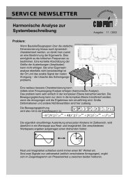
CADFEM INFOPLANER 1/<strong>2007</strong>Mixed Mode Constitutive DriverThe Mixed Mode Constitutive Driver (MMCD) isa new graphical software package that helps theuser to efficiciently evaluate the response of mate-rial models implemented in LS-DYNA, and to fit thematerial model parameters to test data (parameteridentification).32The MMCD calculates the stress-strain behavior of materialmodels driven by combinations of strain increments and stressboundary conditions. Material models access is obtained by linkingthe MMCD to the LS-DYNA library of object files. Parameteridentification proceeds either manually (visual comparisonof plotted material response curve versus test data curve) orautomatically by interfacing the MMCD with the LS-OPT optimizationcode.The MMCD complements the performance of LS-DYNA. Theusefulness of any finite element simulation depends, in part,upon the analyst’s experience and judgment in selectingappropriate material models for a particular application, andthen fitting the numerous material model parameters to testdata. Although parameter identification can be accomplisheddirectly with the LS-DYNA and LS-OPT codes, the MMCD greatlystreamlines the process because of its sole dedication toparameter identification. This streamlined process saves theanalyst significant time and money, and provides an efficientlearning tool for future generations of structural engineers.The MMCD is accurate, efficient, and easy to use. The MMCDis accurate because stress-strain curves calculated with theMMCD are in agreement with single element simulations conductedwith the LS-DYNA code. The MMCD is efficient becausethe time it takes to set-up, run, and plot material model outputwith the MMCD is typically less than that needed to manuallyset-up, run, and plot results of a single element simulation oroptimization problem. The MMCD is easy to use because preandpost-processing are conducted with points and clicks ofthe mouse. Simulation input, computed results, and test dataare easily accessed and stored in the MMCD database for futureplotting and manipulation.The main attributes and functions of the MMCD include:• Web downloadable software package (pre-processor, driver,post-processor, database, test data, libraries) that operatesseamlessly as a single, easy to use code. The MMCD executableand associated files reside on user’s network and rununder Windows 2000 or Windows XP.• Graphical user interface (GUI) to facilitate selection of thematerial model constants, desired load histories, test datacurves, and LS-OPT optimization parameters.• Microsoft Jet database, freely distributed with the MMCD, inwhich all simulation input, computed output, and test dataare stored. New information is stored in the database forlater use (and re-use) every time a user saves new materialmodel properties, load definitions, or defines new optimizationproblems.• Access to select LS-DYNA material models. Material modelscurrently interfaced are MAT_003 (plastic-kinematic),MAT_024 (piecewise_linear_plasticity), MAT_143 (wood),MAT_147 (soil), and MAT_159 (concrete continuous surfacecap model). Material response may include elastic, plastic,damage, and high strain rate behaviors. More materialmodels will be added in future releases in response to userdemand.• An interface for a user-defined material model (MAT_041).This interface is useful for analysts who wish to develop theirown proprietary material models. A FORTRAN compiler isrequired to create the executable.• A library of predefined load histories that simulate commonlaboratory tests. These include combinations of uniaxial/biaxial/triaxial compression and tension, pure and simpleshear stress, all with unloading and reloading to zero stressor zero strain (see Fig. 1).• An optional method for inputting user-specified load histories.Fig. 1: The MMCD uses internal feedback to load, unload to zero stress,and then reload (wood model 143 run parallel to the wood grain).Software
CADFEM INFOPLANER 1/<strong>2007</strong>• A database of material propertytest data for concrete,wood, and soil. Additional testdata will be added in futurereleases. Test data contributionsfrom users are welcome.• A read curve capability forincorporating user-specific testdata. This feature is useful forplotting newly acquired dataor for data that is proprietaryto the user.• An automated procedure forfitting each material modelto test data by interfacing theMMCD with the LS-OPT code (Fig. 2). The MMCD queriesthe user for the pertinent LS-OPT input, creates the LS-OPTinput file, executes the LS-OPT code, then gathers and plotsthe results. Results automatically plotted include optimizedfits of the material model response to test data (Fig. 3), andvalues of fitted material model parameters versus iterationnumber.• The capability to create report-quality graphs using ScalarVector Graphics. Graphs may be plotted with multiple curveswith x-axis and y-axis components selected from listings ofstress, strain, principal stress, principal strain, and invariants.The user may also select preferences for font type/size/colorand curve colors/styles/symbols.• The capability to manipulate plotted curves via cross-plots,integration, shifting, subtraction, and swaping of the x andy axes. These features are useful for converting units ormanipulating test data so that it correlates with computedresponse.• The capability to plot selected 3D yield surfaces, and torotate and translate those surfaces about various axes (Fig.4). Yield surfaces currently implemented include Mohr-Coulomb,Von-Mises, linear and parabolic Drucker Prager, Tresca,continuous surface cap (159), wood (143), and soil (147).• The ability to create LS-DYNA material model input files(*MAT portion only) following final selection or fit of materialmodel parameters.• HELP files that include “Getting Started” guidance and examplecalculations, along with instructions and commentaryon each GUI menu, available test data, and MMCD theory.Fig. 2: Example GUI for interfacing LS-OPT with the MMCD.Fig. 3: Example fit of model to concrete data in uniaxial tensile stress.Fig. 4: Example 3D surface showing that concrete model 159 has asmooth intersection between the failure surface and hardening cap.AuthorsYvonne D. Murray; Carolyn M. Yeager, APTEKyvonne@aptek.com and yeager@aptek.comReferencesLSTC, LS-DYNA Keyword User’s Manual, Version 971 Beta,Livermore Software Technology Corporation, LivermoreCalifornia, January <strong>2007</strong>.Stander, N., W. Roux, T.Eggleston, and K. Craig, LS-OPTUser’s Manual, Design Optimization for the EngineeringAnalyst, Version 2.2, Livermore Software Technology Corporation,Livermore California, 2004.Your contact for LS-DYNA and materials modelingDr.-Ing. Matthias Hörmann, CADFEM GmbHPhone +49 (0)8092-7005-41E-Mail mhoermann@cadfem.deA free demonstration version and sales information will beavailable at APTEK’s website www.aptek.com/mmcd in May<strong>2007</strong>. Email the authors or Matthias Hoermann for details.33Software