Infoplaner 1-2007 - Cadfem
Infoplaner 1-2007 - Cadfem
Infoplaner 1-2007 - Cadfem

Erfolgreiche ePaper selbst erstellen
Machen Sie aus Ihren PDF Publikationen ein blätterbares Flipbook mit unserer einzigartigen Google optimierten e-Paper Software.
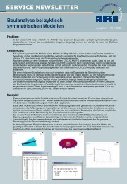
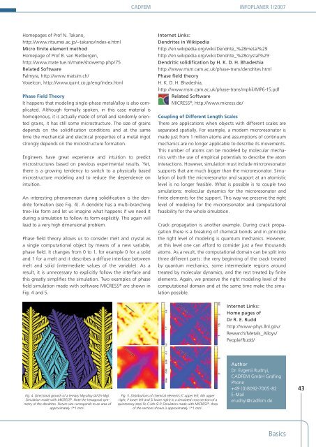
CADFEM INFOPLANER 1/<strong>2007</strong>Homepages of Prof N. Takano,http://www.ritsumei.ac.jp/~takano/index-e.htmlMicro finite element methodHomepage of Prof B. van Rietbergen,http://www.mate.tue.nl/mate/showemp.php/75Related SoftwarePalmyra, http://www.matsim.ch/Voxelcon, http://www.quint.co.jp/eng/index.htmlPhase Field TheoryIt happens that modeling single-phase metal/alloy is also complicated.Although formally spoken, in this case material ishomogenous, it is actually made of small and randomly orientedgrains, it has still some microstructure. The size of grainsdepends on the solidification conditions and at the sametime the mechanical and electrical properties of a metal ingotstrongly depends on the microstructure formation.Engineers have great experience and intuition to predictmicrostructures based on previous experimental results. Yet,there is a growing tendency to switch to a physically basedmicrostructure modeling and to reduce the dependence onintuition.An interesting phenomenon during solidification is the dendriteformation (see Fig. 4). A dendrite has a multi-branchingtree-like form and let us imagine what happens if we need itduring a simulation to follow its form explicitly. This again willlead to a very high dimensional problem.Phase field theory allows us to consider melt and crystal asa single computational object by means of a new variable,phase field. It changes from 0 to 1, for example 0 for a solidand 1 for a melt and it describes a diffuse interface betweenmelt and solid (intermediate values of the variable). As aresult, it is unnecessary to explicitly follow the interface andthis greatly simplifies the simulation. Two examples of phasefield simulation made with software MICRESS ® are shown inFig. 4 and 5.Internet Links:Dendrites in Wikipediahttp://en.wikipedia.org/wiki/Dendrite_%28metal%29http://en.wikipedia.org/wiki/Dendrite_%28crystal%29Dendritic solidification by H. K. D. H. Bhadeshiahttp://www.msm.cam.ac.uk/phase-trans/dendrites.htmlPhase field theoryH. K. D. H. Bhadeshia,http://www.msm.cam.ac.uk/phase-trans/mphil/MP6-15.pdfRelated SoftwareMICRESS ® , http://www.micress.de/Coupling of Different Length ScalesThere are applications when objects with different scales areseparated spatially. For example, a modern microresonator ismade just from 1 million atoms and assumptions of continuummechanics are no longer applicable to describe its movements.This number of atoms can be modeled by molecular mechanicswith the use of empirical potentials to describe the atominteractions. However, simulation must include mircroresonatorsupports that are much bigger than the microresonator. Simulationof both the microresonator and support at an atomisticlevel is no longer feasible. What is possible is to couple twosimulations: molecular dynamics for the microresonator andfinite elements for the support. This way we preserve the rightlevel of modeling for the microresonator and computationalfeasibility for the whole simulation.Crack propagation is another example. During crack propagationthere is a breaking of chemical bonds and in principlethe right level of modeling is quantum mechanics. However,at this level one can afford to consider just a few thousandsatoms. As a result, the computational domain can be split intothree different parts: the very beginning of the crack treatedby quantum mechanics, some intermediate regions aroundtreated by molecular dynamics, and the rest treated by finiteelements. Again, we preserve the right modeling level of thecomputational domain and at the same time make the simulationpossible.Internet Links:Home pages ofDr R. E. Ruddhttp://www-phys.llnl.gov/Research/Metals_Alloys/People/Rudd/Fig. 4. Directional growth of a ternary Mg-alloy (Al-Zn-Mg).Simulation made with MICRESS ® . Note the hexagonal symmetryof the dendrites. Picture size corresponds to an area ofapproximately 1*1 mm 2 .Fig. 5. Distributions of chemical elements (C upper left, Mn upperright, P lower left and Si lower right) in a simulated cross-section of aquinternary steel Fe-C-Mn-Si-P. Simulation made with MICRESS ® . Areaof the sections shown is approximately 1*1 mm 2 .AuthorDr. Evgenii Rudnyi,CADFEM GmbH GrafingPhone+49 (0)8092-7005-82E-Mailerudnyi@cadfem.de43Basics