

2-2018
Fachzeitschrift für Hochfrequenz- und Mikrowellentechnik
Fachzeitschrift für Hochfrequenz- und Mikrowellentechnik

Sie wollen auch ein ePaper? Erhöhen Sie die Reichweite Ihrer Titel.
YUMPU macht aus Druck-PDFs automatisch weboptimierte ePaper, die Google liebt.
RF & Wireless<br />
AA-Series Field Generating Systems<br />
Traditionally,<br />
generating lowlevel<br />
electric fields<br />
in the 18...40 GHz<br />
frequency band has<br />
been performed using<br />
traveling wave tube<br />
amplifiers (TWTA’s).<br />
These TWTAs often<br />
produce much more<br />
power than is actually<br />
required to generate the<br />
required field strengths<br />
while also being an<br />
extremely costly<br />
solution. Why pay for<br />
unnecessary power?<br />
AR rf/microwave Instrumentation<br />
has the answer by introducing<br />
its AA-Series field generating<br />
systems. These systems<br />
can produce field strengths of<br />
up to 50 V/m in the 18...26.5<br />
GHz and 26.5...40 GHz bands.<br />
An AA system is composed of a<br />
solid- state amplifier and antenna<br />
combined in a single housing,<br />
which can then be paired with<br />
a rack-mountable power and RF<br />
routing unit.<br />
AA-Series Basics<br />
The AA-Series products are<br />
designed to be a low-cost and<br />
highly reliable solution to a<br />
decades-old problem of having<br />
to use costly, unreliable TWTAs<br />
to generate low-level, high-frequency<br />
electric fields. Typically,<br />
in the 18...26.5 GHz (K-Band)<br />
and 26.5...40 GHz (Ka-Band),<br />
the smallest-size TWTA available<br />
in terms of RF power is<br />
about 40 Watts, which provides<br />
a solution for field strengths up<br />
to 200 V/m. Until recently, this<br />
has been the only solution for<br />
AR rf/microwave<br />
Instrumentation:<br />
Application Note #75,<br />
AA-Series Field Generating<br />
Systems<br />
www.arworld.us<br />
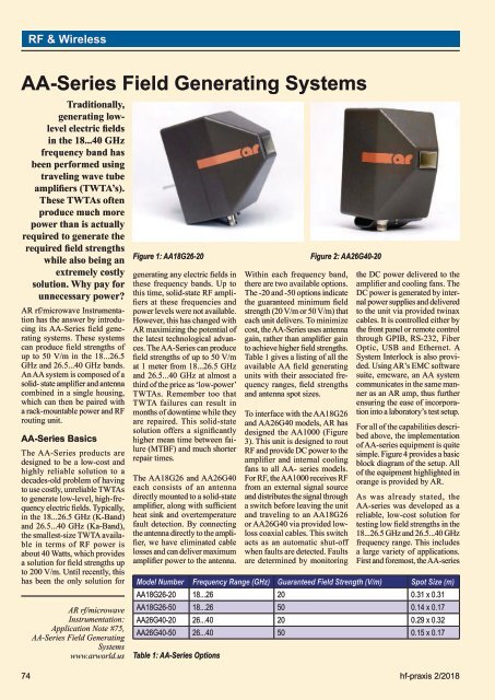
Figure 1: AA18G26-20<br />
generating any electric fields in<br />
these frequency bands. Up to<br />
this time, solid-state RF amplifiers<br />
at these frequencies and<br />
power levels were not available.<br />
However, this has changed with<br />
AR maximizing the potential of<br />
the latest technological advances.<br />
The AA-Series can produce<br />
field strengths of up to 50 V/m<br />
at 1 meter from 18...26.5 GHz<br />
and 26.5...40 GHz at almost a<br />
third of the price as ‘low-power’<br />
TWTAs. Remember too that<br />
TWTA failures can result in<br />
months of downtime while they<br />
are repaired. This solid-state<br />
solution offers a significantly<br />
higher mean time between failure<br />
(MTBF) and much shorter<br />
repair times.<br />
The AA18G26 and AA26G40<br />
each consists of an antenna<br />
directly mounted to a solid-state<br />
amplifier, along with sufficient<br />
heat sink and overtemperature<br />
fault detection. By connecting<br />
the antenna directly to the amplifier,<br />
we have eliminated cable<br />
losses and can deliver maximum<br />
amplifier power to the antenna.<br />
Within each frequency band,<br />
there are two available options.<br />
The -20 and -50 options indicate<br />
the guaranteed minimum field<br />
strength (20 V/m or 50 V/m) that<br />
each unit delivers. To minimize<br />
cost, the AA-Series uses antenna<br />
gain, rather than amplifier gain<br />
to achieve higher field strengths.<br />
Table 1 gives a listing of all the<br />
available AA field generating<br />
units with their associated frequency<br />
ranges, field strengths<br />
and antenna spot sizes.<br />
To interface with the AA18G26<br />
and AA26G40 models, AR has<br />
designed the AA1000 (Figure<br />
3). This unit is designed to rout<br />
RF and provide DC power to the<br />
amplifier and internal cooling<br />
fans to all AA- series models.<br />
For RF, the AA1000 receives RF<br />
from an external signal source<br />
and distributes the signal through<br />
a switch before leaving the unit<br />
and traveling to an AA18G26<br />
or AA26G40 via provided lowloss<br />
coaxial cables. This switch<br />
acts as an automatic shut-off<br />
when faults are detected. Faults<br />
are determined by monitoring<br />
the DC power delivered to the<br />
amplifier and cooling fans. The<br />
DC power is generated by internal<br />
power supplies and delivered<br />
to the unit via provided twinax<br />
cables. It is controlled either by<br />
the front panel or remote control<br />
through GPIB, RS-232, Fiber<br />
Optic, USB and Ethernet. A<br />
System Interlock is also provided.<br />
Using AR’s EMC software<br />
suite, emcware, an AA system<br />
communicates in the same manner<br />
as an AR amp, thus further<br />
ensuring the ease of incorporation<br />
into a laboratory’s test setup.<br />
For all of the capabilities described<br />
above, the implementation<br />
of AA-series equipment is quite<br />
simple. Figure 4 provides a basic<br />
block diagram of the setup. All<br />
of the equipment highlighted in<br />
orange is provided by AR.<br />
As was already stated, the<br />
AA-series was developed as a<br />
reliable, low-cost solution for<br />
testing low field strengths in the<br />
18...26.5 GHz and 26.5...40 GHz<br />
frequency range. This includes<br />
a large variety of applications.<br />
First and foremost, the AA-series<br />
Model Number Frequency Range (GHz) Guaranteed Field Strength (V/m) Spot Size (m)<br />
AA18G26-20 18...26 20 0.31 x 0.31<br />
AA18G26-50 18...26 50 0.14 x 0.17<br />
AA26G40-20 26...40 20 0.29 x 0.32<br />
AA26G40-50 26...40 50 0.15 x 0.17<br />
Table 1: AA-Series Options<br />
Figure 2: AA26G40-20<br />
74 hf-praxis 2/<strong>2018</strong>


