Technical Documentation Pressure Independent Characterized ...
Technical Documentation Pressure Independent Characterized ...
Technical Documentation Pressure Independent Characterized ...

You also want an ePaper? Increase the reach of your titles
YUMPU automatically turns print PDFs into web optimized ePapers that Google loves.
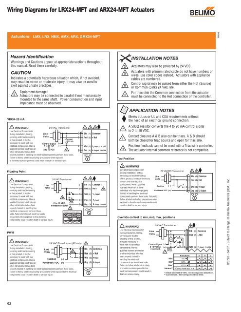
Wiring Diagrams for LRX24-MFT and ARX24-MFT Actuators<br />
VDC/4-20 mA<br />
Floating Point<br />
PWM<br />
62<br />
Actuators: LMX, LRX, NMX, AMX, ARX, GMX24-MFT<br />
Hazard Identification<br />
Warnings and Cautions appear at appropriate sections throughout<br />
INSTALLATION NOTES<br />
this manual. Read these carefully.<br />
3 Actuators may also be powered by 24 VDC.<br />
CAUTION<br />
Indicates a potentially hazardous situation which, if not avoided,<br />
may result in minor or moderate injury. It may also be used to<br />
5<br />
alert against unsafe practices.<br />
8<br />
2<br />
Equipment damage!<br />
Actuators may be connected in parallel if not mechanically<br />
mounted to the same shaft. Power consumption and input<br />
impedance must be observed.<br />
WARNING<br />
Live Electrical Components!<br />
During installation, testing,<br />
servicing and troubleshooting<br />
of this product, it maybe<br />
necessary to work with live<br />
electrical components. Have a<br />
qualified licensed electrician or<br />
other individual who has been<br />
Line<br />
Volts<br />
Control Signal<br />
4 to 20 mA<br />
or<br />
2 to 10 VDC<br />
Line<br />
Volts<br />
24 VAC Transformer<br />
(–)<br />
(+)<br />
24 VAC Transformer (AC only)<br />
Position (–)<br />
Feedback VDC (+)<br />
Ω 500Ω<br />
1/4 watt<br />
properly trained in handling live electrical components perform these tasks.<br />
Failure to follow all electrical safety precautions when exposed<br />
to live electrical components could result in death or serious injury.<br />
WARNING<br />
Live Electrical Components!<br />
During installation, testing,<br />
servicing and troubleshooting<br />
of this product, it maybe<br />
necessary to work with live<br />
electrical components. Have a<br />
qualified licensed electrician or<br />
other individual who has been<br />
properly trained in handling live<br />
electrical components perform these<br />
tasks. Failure to follow all electrical safety<br />
precautions when exposed to live electrical<br />
components could result in death or serious injury.<br />
WARNING<br />
Live Electrical Components!<br />
During installation, testing,<br />
servicing and troubleshooting<br />
of this product, it maybe<br />
necessary to work with live<br />
electrical components. Have a<br />
qualified licensed electrician or<br />
other individual who has been<br />
Line<br />
Volts<br />
7<br />
24 VAC Transformer<br />
properly trained in handling live electrical components perform these tasks.<br />
Failure to follow all electrical safety precautions when exposed to live electrical<br />
components could result in death or serious injury.<br />
8<br />
2 to 10 VDC<br />
Feedback Signal<br />
A<br />
B<br />
9<br />
11<br />
Direction of rotation switch<br />
CCW<br />
CCW<br />
CW<br />
CW<br />
A B 5<br />
8<br />
A B 5<br />
2<br />
Blk (1) Common<br />
Red (2) + Hot<br />
Wht (3) Y1 Input, 2 to 10V<br />
Grn (5) U Output, 2 to 10V<br />
CCW CW<br />
2<br />
2<br />
3 5<br />
3<br />
Blk (1) Common –<br />
Red (2) Hot + 10<br />
Wht (3) Y1 Input<br />
Pnk (4) Y2 Input<br />
Org (5) U Output 2 to 10V<br />
Blk (1) Common<br />
Red (2) + Hot<br />
Wht (3) Y Input<br />
Org (5) U Output<br />
7<br />
9<br />
11<br />
10<br />
Two Position<br />
Actuators with plenum rated cable do not have numbers on<br />
wires; use color codes instead. Actuators with appliance<br />
cables are numbered.<br />
Control signal may be pulsed from either the Hot (Source)<br />
or Common (Sink) 24 VAC line.<br />
For triac sink the Common connection from the actuator<br />
must be connected to the Hot connection of the controller.<br />
APPLICATION NOTES<br />
Meets cULus or UL and CSA requirements without<br />
the need of an electrical ground connection.<br />
A 500Ω resistor converts the 4 to 20 mA control signal<br />
to 2 to 10 VDC.<br />
Contact closures A & B also can be triacs. A & B should<br />
both be closed for triac source and open for triac sink.<br />
Position feedback cannot be used with a Triac sink controller.<br />
The actuator internal common reference is not compatible.<br />
WARNING<br />
Live Electrical Components!<br />
During installation, testing,<br />
24 VAC/DC Transformer<br />
servicing and troubleshooting Line<br />
of this product, it maybe necessary<br />
to work with live electrical<br />
Volts<br />
components. Have a qualified<br />
licensed electrician or other<br />
Position (–)<br />
a<br />
individual who has been properly<br />
trained in handling live electrical<br />
Feedback VDC (+)<br />
components perform these tasks. Failure to<br />
follow all electrical safety precautions when<br />
exposed to live electrical components could<br />
result in death or serious injury.<br />
Override control to min, mid, max, positions<br />
WARNING<br />
24 VAC Transformer<br />
Live Electrical Components!<br />
During installation, testing,<br />
servicing and trouble<br />
Line<br />
Volts<br />
shooting of this product,<br />
it maybe necessary to<br />
Ω<br />
work with live electrical Control Signal (–)<br />
components. Have a<br />
qualified licensed electrician<br />
or other individual who has<br />
been properly trained in<br />
2-10 VDC or (+)<br />
4 to 20 mA 500Ω<br />
1/4 watt<br />
7<br />
handling live electrical<br />
Min*<br />
components perform these tasks.<br />
Mid*<br />
Failure to follow all electrical safety<br />
Max*<br />
precautions when exposed to live<br />
electrical components could result in<br />
death or serious injury.<br />
Normal**<br />
A<br />
B<br />
C<br />
Functions<br />
0%<br />
50%<br />
100%<br />
Control mode acc. to Y<br />
Blk (1) Common<br />
Red (2) Hot<br />
Wht (3) Y Input<br />
Org (5) U Output<br />
Blk (1) Common<br />
Red (2) + Hot<br />
Wht (3) Y 1 Input, 2 to 10V<br />
a b c<br />
* Default selectable 0-100%. See Configuration Data Sheet.<br />
** Customizable. See Configuration Data Sheet.<br />
3<br />
2 3<br />
®<br />
W400<br />
J20728 - 04/07 - Subject to change. © Belimo Aircontrols (USA), Inc.