Threads and Threading - Sportpilot.info
Threads and Threading - Sportpilot.info
Threads and Threading - Sportpilot.info

Create successful ePaper yourself
Turn your PDF publications into a flip-book with our unique Google optimized e-Paper software.
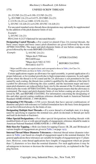
1776 UNIFIED SCREW THREADS<br />
10–32 UNF-2A (22) or 0.190–32 UNF-2A (22)<br />
7<br />
⁄16 –20 UNRF-2A (23) or 0.4375–20 UNRF-2A (23)<br />
2–12 UN-2A (21) or 2.000–12 UN-2A (21)<br />
1 ⁄4–20 UNC-3A-LH (21) or 0.250–20 UNC-3A-LH (21)<br />
For uncoated st<strong>and</strong>ard series threads these designations may optionally be supplemented<br />
by the addition of the pitch diameter limits of size.<br />
Example:<br />
1<br />
⁄4 –20 UNC-2A (21)<br />
PD 0.2164–0.2127 (Optional for uncoated threads)<br />
Designating Coated <strong>Threads</strong>.—For coated (or plated) Class 2A external threads, the<br />
basic (max) major <strong>and</strong> basic (max) pitch diameters are given followed by the words<br />
AFTER COATING. The major <strong>and</strong> pitch diameter limits of size before coating are also<br />
given followed by the words BEFORE COATING.<br />
Example:<br />
Machinery's H<strong>and</strong>book 27th Edition<br />
3 ⁄4 –10 UNC-2A (21)<br />
a Major dia 0.7500 max<br />
PD 0.6850 max<br />
b Major dia 0.7482–0.7353<br />
} AFTER COATING<br />
}<br />
BEFORE COATING<br />
PD 0.6832–0.6773 }<br />
Certain applications require an allowance for rapid assembly, to permit application of a<br />
proper lubricant, or for residual growth due to high-temperature expansion. In such applications<br />
where the thread is to be coated <strong>and</strong> the 2A allowance is not permitted to be consumed<br />
by such coating, the thread class symbol is qualified by the addition of the letter G<br />
(symbol for allowance) following the class symbol, <strong>and</strong> the maximum major <strong>and</strong> maximum<br />
pitch diameters are reduced below basic size by the amount of the 2A allowance <strong>and</strong><br />
followed by the words AFTER COATING. This arrangement ensures that the allowance is<br />
maintained. The major <strong>and</strong> pitch diameter limits of size before coating are also given followed<br />
by SPL <strong>and</strong> BEFORE COATING. For <strong>info</strong>rmation concerning the designating of<br />
this <strong>and</strong> other special coating conditions reference should be made to American National<br />
St<strong>and</strong>ard ASME/ANSI B1.1-1989 (R2001).<br />
Designating UNS <strong>Threads</strong>.—UNS screw threads that have special combinations of<br />
diameter <strong>and</strong> pitch with tolerance to Unified formulation have the basic form designation<br />
set out first followed always by the limits of size.<br />
Designating Multiple Start <strong>Threads</strong>.—If a screw thread is of multiple start, it is designated<br />
by specifying in sequence the nominal size, pitch (in decimals or threads per inch)<br />
<strong>and</strong> lead (in decimals or fractions).<br />
Other Special Designations.—For other special designations including threads with<br />
modified limits of size or with special lengths of engagement, reference should be made to<br />
American National St<strong>and</strong>ard ASME/ANSI B1.1-1989 (R2001).<br />
Hole Sizes for Tapping.—Hole size limits for tapping Classes 1B, 2B, <strong>and</strong> 3B threads of<br />
various lengths of engagement are given in Table 2 on page 1925.<br />
Internal Thread Minor Diameter Tolerances.—Internal thread minor diameter tolerances<br />
in Table 3 are based on a length of engagement equal to the nominal diameter. For<br />
general applications these tolerances are suitable for lengths of engagement up to 11 ⁄ 2 diameters.<br />
However, some thread applications have lengths of engagement which are greater<br />
than 11 a Major <strong>and</strong> PD values are equal to basic <strong>and</strong> correspond to those in Table 3 for Class 3A.<br />
b Major <strong>and</strong> PD limits are those in Table 3 for Class 2A.<br />
⁄ 2 diameters or less than the nominal diameter. For such applications it may be<br />
advantageous to increase or decrease the tolerance, respectively, as explained in the Tapping<br />
Section.<br />
Copyright 2004, Industrial Press, Inc., New York, NY