StringPin Pinsetter Service Manual - Brunswick
StringPin Pinsetter Service Manual - Brunswick
StringPin Pinsetter Service Manual - Brunswick

Create successful ePaper yourself
Turn your PDF publications into a flip-book with our unique Google optimized e-Paper software.
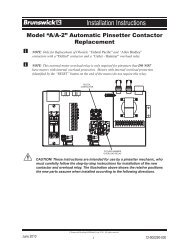
The following is a description of the Inter face boxes’ components and connections.<br />
(1) Odd Switches (J1) - Input for the “<strong>Pinsetter</strong> ON/Scorer Enabled” switch, “Ball<br />
Detect On/Off” switch and “Reset” (cycle) switch on the enclosure for the left/odd<br />
pinsetter.<br />
(2) Spare Outputs (J2) - Unused outputs.<br />
(3) Even Switches (J3) - Input for the “<strong>Pinsetter</strong> ON/Scorer Enabled” switch, “Ball<br />
Detect On/Off” switch and “Reset” (cycle) switch on the enclosure for the right/even<br />
pinsetter.<br />
(4) Alert Led (J4) - Used for an enclosure mounted LED. When it is on, at least one<br />
of the pinsetters has either been manually turned on with the toggle switch on the<br />
enclosure or has turned off the ball detects.<br />
(5) Odd Pin Switches (J5) - Input for the signals from the pin switches and quick set<br />
(on the Mendes pinsetters) on the left/odd pinsetter.<br />
(6) Reset Bypass (J6) - Connection to allow the ball rack reset buttons to directly<br />
control the pinsetters, instead of having the interface board control when to reset the<br />
pins.<br />
(7) Odd <strong>Pinsetter</strong> Power/Reset (J7) - Connection to the left/odd lane pinsetter. The<br />
interface PCB can turn the left/odd lane pinsetter on/off and reset (cycle) the pinset<br />
ter through this connection.<br />
(8) Ball Rack Reset Input (J8) - Input for the ball rack reset buttons. The interface<br />
board will control when the ball rack reset buttons will reset the pins. Keeps the<br />
pinsetter and scorer in sync.<br />
(9) Left/Odd Ball Detect (J9) - Connection for the signal and power for the odd lane<br />
ball detector.<br />
(10) Right/Even Ball Detect (J10) - Connection for the signal and power for the even<br />
lane ball detector.<br />
(11) Foul (J11) - Input for the signals from the foul units for both the left and right lanes.<br />
Also refer to (15) Foul Jumper (JP4).<br />
(12) Bumpers (J12) - Connection to AMF/Qubica automated bumpers.<br />
(13) Right/Even <strong>Pinsetter</strong> Power/Reset (J13) - Connection to the even lane pinsetter.<br />
The distribution PCB can turn the even lane pinsetter on/off and reset (cycle) the<br />
pinsetter through this connection<br />
(14) Even Pin Switches (J14) - Input for the signals from the pin switches and quick set<br />
(on the Mendes pinsetters) on the right/even pinsetter.<br />
(15) Serial COM (J15) -<br />
(16) Watch Dog Timer (JP1) - open watchdog disabled<br />
<strong>StringPin</strong> <strong>Pinsetter</strong> <strong>Service</strong> <strong>Manual</strong> 59