Vertical mill installation instructions - Haas Automation, Inc.
Vertical mill installation instructions - Haas Automation, Inc.
Vertical mill installation instructions - Haas Automation, Inc.

You also want an ePaper? Increase the reach of your titles
YUMPU automatically turns print PDFs into web optimized ePapers that Google loves.
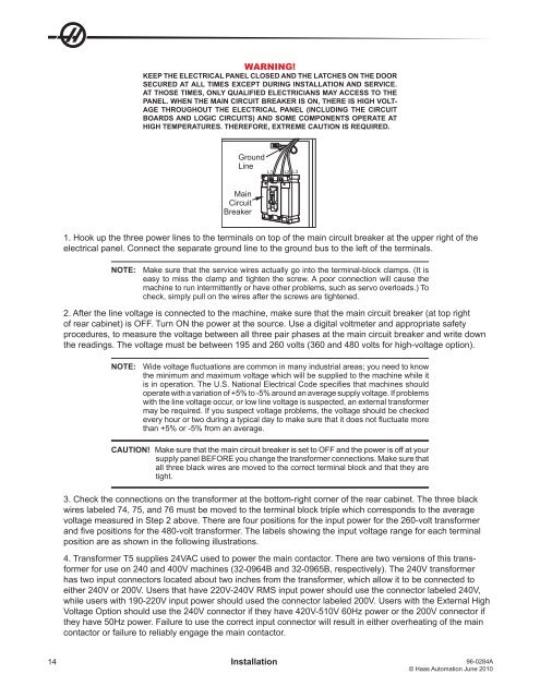
WARNING!<br />
KEEP THE ELECTRICAL PANEL CLOSED AND THE LATCHES ON THE DOOR<br />
SECURED AT ALL TIMES EXCEPT DURING INSTALLATION AND SERVICE.<br />
AT THOSE TIMES, ONLY QUALIFIED ELECTRICIANS MAY ACCESS TO THE<br />
PANEL. WHEN THE MAIN CIRCUIT BREAKER IS ON, THERE IS HIGH VOLT-<br />
AGE THROUGHOUT THE ELECTRICAL PANEL (INCLUDING THE CIRCUIT<br />
BOARDS AND LOGIC CIRCUITS) AND SOME COMPONENTS OPERATE AT<br />
HIGH TEMPERATURES. THEREFORE, EXTREME CAUTION IS REQUIRED.<br />
Ground<br />
Line<br />
Main<br />
Circuit<br />
Breaker<br />
L1 L2 L3<br />
1. Hook up the three power lines to the terminals on top of the main circuit breaker at the upper right of the<br />
electrical panel. Connect the separate ground line to the ground bus to the left of the terminals.<br />
NOTE: Make sure that the service wires actually go into the terminal-block clamps. (It is<br />
easy to miss the clamp and tighten the screw. A poor connection will cause the<br />
machine to run intermittently or have other problems, such as servo overloads.) To<br />
check, simply pull on the wires after the screws are tightened.<br />
2. After the line voltage is connected to the machine, make sure that the main circuit breaker (at top right<br />
of rear cabinet) is OFF. Turn ON the power at the source. Use a digital voltmeter and appropriate safety<br />
procedures, to measure the voltage between all three pair phases at the main circuit breaker and write down<br />
the readings. The voltage must be between 195 and 260 volts (360 and 480 volts for high-voltage option).<br />
NOTE: Wide voltage fluctuations are common in many industrial areas; you need to know<br />
the minimum and maximum voltage which will be supplied to the machine while it<br />
is in operation. The U.S. National Electrical Code specifies that machines should<br />
operate with a variation of +5% to -5% around an average supply voltage. If problems<br />
with the line voltage occur, or low line voltage is suspected, an external transformer<br />
may be required. If you suspect voltage problems, the voltage should be checked<br />
every hour or two during a typical day to make sure that it does not fluctuate more<br />
than +5% or -5% from an average.<br />
CAUTION! Make sure that the main circuit breaker is set to OFF and the power is off at your<br />
supply panel BEFORE you change the transformer connections. Make sure that<br />
all three black wires are moved to the correct terminal block and that they are<br />
tight.<br />
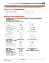
3. Check the connections on the transformer at the bottom-right corner of the rear cabinet. The three black<br />
wires labeled 74, 75, and 76 must be moved to the terminal block triple which corresponds to the average<br />
voltage measured in Step 2 above. There are four positions for the input power for the 260-volt transformer<br />
and five positions for the 480-volt transformer. The labels showing the input voltage range for each terminal<br />
position are as shown in the following illustrations.<br />
4. Transformer T5 supplies 24VAC used to power the main contactor. There are two versions of this transformer<br />
for use on 240 and 400V machines (32-0964B and 32-0965B, respectively). The 240V transformer<br />
has two input connectors located about two inches from the transformer, which allow it to be connected to<br />
either 240V or 200V. Users that have 220V-240V RMS input power should use the connector labeled 240V,<br />
while users with 190-220V input power should used the connector labeled 200V. Users with the External High<br />
Voltage Option should use the 240V connector if they have 420V-510V 60Hz power or the 200V connector if<br />
they have 50Hz power. Failure to use the correct input connector will result in either overheating of the main<br />
contactor or failure to reliably engage the main contactor.<br />
14 Installation 96-0284A<br />
© <strong>Haas</strong> <strong>Automation</strong> June 2010