Vertical mill installation instructions - Haas Automation, Inc.
Vertical mill installation instructions - Haas Automation, Inc.
Vertical mill installation instructions - Haas Automation, Inc.

You also want an ePaper? Increase the reach of your titles
YUMPU automatically turns print PDFs into web optimized ePapers that Google loves.
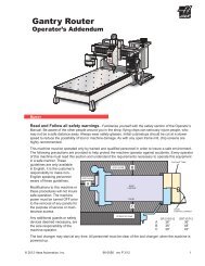
4. Hoist the tool changer rear mount into place and mount it with six 1/2"-13 x 1 1/4" SHCS, two 1/2"-13 x 3"<br />
SHCS, and two spacers.<br />
5. Carefully swing the tool changer into place. Attach the air cylinder rod with the 5/8"-11 x 7" SHCS. Attach<br />
the stabilizer rod with the 1/2 x 5" SHCS.<br />
6. Mount the tool changer link to the rear mount with two 1/2"-13 x 1 1/4" and the shaft link.<br />
7. Connect the air lines (2) at each end of the air cylinder. IMPORTANT! The air line from the bottom fitting of<br />
the lube/air panel connects to the rear fitting on the air cylinder. The air line from the top fitting of the lube/air<br />
panel connects to the front fitting on the air cylinder.<br />
8. Hoist the tool changer enclosure into place, so that it protrudes from the rear of the machine. Attach it with<br />
the 18 BHCS. Attach the bracket from the column to the tool changer enclosure with 6 BHCS.<br />
tool chanGeR aliGnMent (vR seRies)<br />
This procedure will align the tool changer to the spindle in the Y-axis.<br />
1. Zero Return All Axes. Place cardboard on the table for protection.<br />
2. Place a tool in the spindle. Press the ORIENT SPINDLE key. Ensure there is no tool in the tool changer<br />
pocket facing the spindle. Press Emergency Stop.<br />
3. Swing the tool changer into the tool change position by hand. Mark the top of the tool changer link with<br />
paint to establish an initial position.<br />
NOTE: Ensure the spindle does not spin. When E-Stop is pressed, the spindle is free to<br />
rotate, and may lose its orientation.<br />
4. Check the tool changer pocket position in relation to the tool in the spindle. If the tool changer is misaligned<br />
in the Y-axis, continue with this procedure. If the tool changer is misaligned in the X-axis, contact the Service<br />
Department at <strong>Haas</strong> <strong>Automation</strong>.<br />
22 Installation 96-0284A<br />
© <strong>Haas</strong> <strong>Automation</strong> June 2010<br />
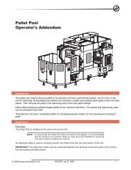
Link<br />
Locknut (2)<br />
5. Loosen the locknut at each end of the tool changer link. Note that one is a left-hand thread and one is a<br />
right-hand thread. Once the locknuts are loose, rotate the link clockwise, and then counterclockwise until<br />
resistance is felt in each direction. Rotate the link to the center of the area in which the link turns freely.<br />
6. Tighten the locknuts at each end, while holding the link in place with a wrench.<br />
7. Push the tool changer away from the spindle. Zero Return All Axes, and the tool changer should move back<br />
to the HOME (out of the work envelope) position.<br />
8. Run a number of tool changes, and ensure they are performed smoothly. If not, perform this procedure<br />
again.