Vertical mill installation instructions - Haas Automation, Inc.
Vertical mill installation instructions - Haas Automation, Inc.
Vertical mill installation instructions - Haas Automation, Inc.

Create successful ePaper yourself
Turn your PDF publications into a flip-book with our unique Google optimized e-Paper software.
1. Connect the hose attached to the machine’s head to the hose connection on the Standard Coolant Pump.<br />
2. Separate the hose coming from the top of the Auxiliary Filter from the hose coming from the bottom. They<br />
have been connected together for shipping.<br />
3. Attach Auxiliary Filter male connector (top hose) to female connector on TSC Coolant Pump Assembly.<br />
4. Attach the Auxiliary Filter female connector (bottom hose) to the short hose with the male connector on the<br />
TSC Coolant Pump Assembly.<br />
5. Connect the plastic tubing (tied to the Auxiliary Filter) from the small elbow fitting on the top of the Auxiliary<br />
Filter to the small elbow fitting on the Standard Coolant Pump hose connector.<br />
6. Connect the hose attached to the TSC Coolant Pump Assembly to the TSC Filter Assembly.<br />
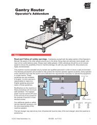
chip auGeR <strong>installation</strong><br />
1. Unpack the auger and discharge tube.<br />
Set<br />
Screw<br />
Motor Hub<br />
Auger<br />
2. Slide the auger into the discharge tube opening and then slip the opposite end onto the motor hub. Fasten<br />
it to the motor hub with the 5/16-18 x 2½" bolt.<br />
3. Install the gasket and slide the discharge tube up and onto the studs. Attach the eight nuts with locking<br />
washers and tighten uniformly.<br />
4. After machine start-up, check auager operation to ensure the direction of rotation will move the chips<br />
toward the discharge tube. If the auger is turning so that the chips are not being moved toward the discharge<br />
tube, change the bit switch in “REV CONVEYOR” from 1 to 0 or 0 to 1 to establish a new forward direction.<br />
VF-1/2 with 95-Gallon Coolant Tank<br />
"Clock" the chip chute in a VF-1 or VF-2 with a 95-gallon coolant tank to accommodate a chip container.<br />
Rotate the chip chute mounting flange one bolt hole toward the front of the machine. Refer to the following<br />
illustrations to verify correct orientation. Secure the chute with the provided bolts.<br />
36 Installation 96-0284A<br />
© <strong>Haas</strong> <strong>Automation</strong> June 2010