Vertical mill installation instructions - Haas Automation, Inc.
Vertical mill installation instructions - Haas Automation, Inc.
Vertical mill installation instructions - Haas Automation, Inc.

You also want an ePaper? Increase the reach of your titles
YUMPU automatically turns print PDFs into web optimized ePapers that Google loves.
Machine RequiReMents<br />
96-0284A<br />
© <strong>Haas</strong> <strong>Automation</strong> June 2010<br />
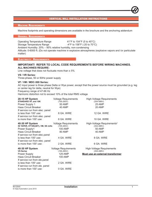
VERTICAL MILL INSTALLATION INSTRUCTIONS<br />
Machine footprints and operating dimensions are available in the brochure and the anchoring addendum<br />
GeneRal RequiReMents<br />
Operating Temperature Range 41°F to 104°F (5 to 40°C)<br />
Storage Temperature Range -4°F to 158°F (-20 to 70°C)<br />
Ambient Humidity: 20% – 95% relative humidity, non-condensing<br />
Altitude: 0-6000 ft. (Do not operate machine in explosive atmospheres (explosive vapors and /or particulate<br />
matter)<br />
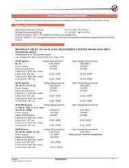
electRicity RequiReMents<br />
IMPORTANT! REFER TO LOCAL CODE REQUIREMENTS BEFORE WIRING MACHINES.<br />
ALL MACHINES REQUIRE:<br />
Line voltage that does not fluctuate more than ± 5%<br />
VS / VR Series:<br />
Three-phase, 50 or 60Hz power supply<br />
VF / VM / MDC-500 Series:<br />
AC input power is three phase Delta or Wye power, except that the power source must be grounded (e.g. leg<br />
or center leg for delta, neutral for Wye)<br />
Frequency range of 47-66 Hz<br />
Harmonic distortion not to exceed 10% of the total RMS voltage<br />
20-15 HP System Voltage Requirements High-Voltage Requirements<br />
STANDARD VF, and 10K (195-260V) (354-488V)<br />
Power Supply 1 50 AMP 25 AMP<br />
<strong>Haas</strong> Circuit Breaker 40 AMP 20 AMP<br />
If service run from elec. panel<br />
is less than 100' use: 8 GA. WIRE 12 GA. WIRE<br />
If service run from elec. panel<br />
is more than 100' use: 6 GA. WIRE 10 GA. WIRE<br />
40-30 HP System Voltage Requirements High-Voltage Requirements 2<br />
50 TAPER, HT10K(40T), VM, SS <strong>mill</strong>s (195-260V) (354-488V)<br />
Power Supply1 100 AMP 50 AMP<br />
<strong>Haas</strong> Circuit Breaker 80 AMP 40 AMP<br />
If service run from elec.panel<br />
is less than 100' use: 4 GA. WIRE 8 GA. WIRE<br />
If service run from elec. panel<br />
is more than 100' use: 2 GA. WIRE 6 GA. WIRE<br />
40-30 HP System Voltage Requirements High-Voltage Requirements<br />
VS Series (195-260V) (354-488V)<br />
Power Supply 125 AMP Must use an external transformer<br />
<strong>Haas</strong> Circuit Breaker 100 AMP<br />
If service run from ele.panel<br />
is less than 100' use: 2 GA. WIRE<br />
If service run from ele. panel<br />
is more than 100' use: 0 GA. WIRE<br />
Installation<br />
1
WARNING!<br />
For operator safety and proper operation, a separate earth ground wire of the same conductor size as the<br />
input power must be connected to the machine chassis. This ground wire is required for operator safety and<br />
for proper operation. This ground must be supplied from the main plant ground at the service entrance, and<br />
should be routed in the same conduit as the input power to the machine. A local cold water pipe or ground<br />
rod adjacent to the machine cannot be used for this purpose.<br />
Input power to the machine must be grounded. For wye power, the neutral must be grounded. For delta<br />
power, a central leg ground or one leg ground should be used. The machine will not function properly on<br />
ungrounded power. (This is not a factor with the External 480V Option.)<br />
The rated horsepower of the machine may not be achieved if the imbalance of the incoming voltage is beyond<br />
an acceptable limit. The machine may function properly, yet may not deliver the advertised power. This is<br />
noticed more often when using phase converters. A phase converter should only be used if all other methods<br />
cannot be used.<br />
The maximum leg-to-leg or leg-to-ground voltage should not exceed 260 volts, or 504 volts for high-voltage<br />
machines with the Internal High Voltage Option.<br />
1 The current requirements shown in the table reflect the circuit breaker size internal to the machine. This<br />
breaker has an extremely slow trip time. It may be necessary to size the external service breaker up by 20-<br />
25%, as indicated by “power supply”, for proper operation.<br />
2 The high-voltage requirements shown reflect the Internal 400V configuration which is standard on European<br />
machines. Domestic and all other users must use the External 480V option.<br />
aiR RequiReMents<br />
Machine Type Main Air Regulator Input Air Line Hose Size<br />
40-Taper VF-1 through VF-11, VM 85psi 3/8”<br />
50-Taper VF-1 through VF-11 85psi 1/2”<br />
VR, VS and MDC Series 85psi 1/2”<br />
The VF, VM and VS series machines requires a minimum of 100 psi at 4 scfm (VR-11 requires a minimum of<br />
100 PSI at 9scfm) at the input to the pressure regulator on the back of the machine. This should be supplied<br />
by at least a two-horsepower compressor, with a minimum 20-gallon tank, that turns on when the pressure<br />
drops to 100 psi.<br />
NOTE: Add 2 scfm to the above minimum air requirements if the operator will be using the<br />
air nozzle during pneumatic operations.<br />
The recommended method of attaching the air hose is to the barb fitting at the back of the machine with a<br />
hose clamp. If a quick coupler is desired, use a 3/8" for 40 taper machines, or a 1/2" for 50 taper machines<br />
and machines with the side mount tool changer option.<br />
Excessive oil and water in the air supply will cause the machine to malfunction. The air filter/regulator has<br />
an automatic bowl dump that should be empty before starting the machine. This must be checked for proper<br />
operation monthly. Also, excessive contaminants in the air line may clog the dump valve and cause oil and/or<br />
water to pass into the machine.<br />
NOTE: The nipple between the air filter/regulator and the oil lubricator reservoir tank is for<br />
the optional rotary table. DO NOT use this as a connection for an auxiliary air line.<br />
Auxiliary connections should be made on the left side of the air filter/regulator.<br />
WARNING!<br />
WHEN THE MACHINE IS OPERATING AND THE PRESSURE GAUGE (ON<br />
THE MACHINE REGULATOR) DROPS BY MORE THAN 10 PSI DURING TOOL<br />
CHANGES, INSUFFICIENT AIR IS BEING SUPPLIED TO THE MACHINE.<br />
2 Installation 96-0284A<br />
© <strong>Haas</strong> <strong>Automation</strong> June 2010
<strong>installation</strong> tools RequiRed<br />
Precision bubble level (0.0005 inch per 10") Test indicator (0.0005)<br />
1 1/8" hex wrench or ratchet Two 3/4" hex wrenches (open-end/box and ratchet)<br />
1 1/2" wrench Claw hammer<br />
Allen Wrenches (VR models) 9/16 hex wrench<br />
(VR models) 12” Adjustable Wrench<br />
Forklift with the following specifications:<br />
96-0284A<br />
© <strong>Haas</strong> <strong>Automation</strong> June 2010<br />
VF-1 VF-2 VF-3 VF-4 VF-5/40 VF-5/50 VF-6 VF-7 VF-8 VF-9 VF-10 VF-11<br />
Machine Weight 7,100 8,000 12,500 13,300 14,600 16,100 21,000 23,000 24,000 25,000 28,000 29,400<br />
Fork Length 8' 8' 8' 8' 8' 8' 8' 8' 8' 8' 8' 8'<br />
* The forklift must be capable of lifting at least this weight.<br />
VR: Forklift must be capable of lifting at least 35, 000 lbs, with forks at least 8’ long.<br />
VS: Forklift must be capable of lifting more than 40,000 lbs, with forks at least 8’ long by 6’ wide.<br />
MateRials RequiRed<br />
Wire and air hose or piping as specified in the Service Requirements section,<br />
A small amount of grease,<br />
Way lube for the lubricator (Vactra #2).<br />
Coolant (water-soluble synthetic, or cutting oil)<br />
MovinG the cRate<br />
CAUTION! THE VMC CRATE CAN ONLY BE MOVED WITH A FORKLIFT.<br />
FORK FORK<br />
CAUTION! The fork positions are marked on the crate. (Also, note that there are three skids<br />
at each side of the pallet. The heavy part of the machine [the back] is positioned<br />
over the two skids that are closest together.) If the fork positions are ignored,<br />
the retaining bolts could be sheared off by the forks or the machine could tip<br />
over when it is picked up.<br />
Installation<br />
3
unpackinG the Mill<br />
1. Remove plastic cover.<br />
CAUTION! Do not put pressure on the top of the machine as you remove the plastic.<br />
2. Remove the coolant tank and the cleats that held it in place.<br />
Shipping<br />
Bracket<br />
Coupler<br />
Assembly<br />
Pallet<br />
3. Unbolt the shipping brackets.<br />
Shock Mount<br />
Rubber Pad<br />
Set Screw<br />
All set screws are needed for<br />
<strong>installation</strong><br />
DO NOT DISCARD!<br />
4. Remove the nuts on the leveling screws holding the shipping bracket to the base casting. Remove the<br />
shipping brackets.<br />
5. Lift the machine off the pallet.<br />
settinG in place<br />
Keep in mind when moving the VF, VM, and VR models, much of its weight is concentrated in the column at<br />
the back. When lifting these <strong>mill</strong>s from the side, it is important that the forks of the forklift be positioned as<br />
close to the back of the machine as possible without being on the pads.<br />
CAUTION! Do not lift the machine any farther than necessary off the floor when moving it,<br />
and move as slowly and cautiously as possible. Dropping the machine, even<br />
from a height of a few inches, can cause injury, result in expensive repairs, and<br />
void the warranty.<br />
VF 1-2 and VM-2: The only acceptable way to move this <strong>mill</strong> is to pick it up from the SIDE with a forklift.<br />
Follow the machine weight and fork length specifications described earlier. The forks must be set as far apart<br />
as possible without being on the pads. The forks must be positioned all the way to the back of the VMC and<br />
they must extend at least 3" past the far side of the machine base. Also, there must be about approximately 6"<br />
clearance between the forklift and the side of the machine.<br />
VF 3-11 and VR-11: Lift from the BACK of the machine with a forklift. Follow the machine weight and fork<br />
length specifications described earlier. There must be approximately 6" clearance between the forklift and the<br />
back of the machine.<br />
Attempting to move the machine any other way may void the warranty.<br />
CAUTION! When lifting the machine with a forklift, be careful not to damage the sheet metal<br />
aprons with the forks.<br />
4 Installation 96-0284A<br />
© <strong>Haas</strong> <strong>Automation</strong> June 2010
96-0284A<br />
© <strong>Haas</strong> <strong>Automation</strong> June 2010<br />
3"<br />
Installation<br />
Min. 6"<br />
Clearance<br />
VF 1 and 2 VF 3 through 11<br />
1. Lift the machine clear of the pallet.<br />
2. Thread the leveling screws through the casting until they extend about an inch out of the bottom of the<br />
machine. If a screw is excessively hard to turn, remove it, dress the threads in the hole with a 1-14 UNC<br />
tap, and inspect the screw. If the screw has dings, dress the threads with a 60 o V file. (You must have good<br />
control over these screws because they are used to precision level the machine.)<br />
3. Move the machine to where it will be located. Grease the dimple in each leveling pad and locate them<br />
under the leveling screws at the four corners. Then lower the machine.<br />
4. Remove all banding and packing material around the control panel and the doors.<br />
5. On the VF-6/8 and VR series, remove the pendant support.<br />
6. Remove the control arm shipping brace. On the VF-3/4, swing the control arm into position and bolt it to the<br />
support on the top front of the machine enclosure. On the VF-6/8, swing control arm to the proper position.<br />
settinG the Machine in place (vs)<br />
Ensure the anchoring preparations are in accordance with the anchoring <strong>instructions</strong> prior to setting the<br />
machine in place.<br />
1. Prepare the table base for mating<br />
• Remove the X-axis auger and auger trough<br />
• Stone and clean thoroughly the mating flange surface. This is an extremely important step that must be<br />
well and properly done before the bases are moved into position with respect to each other. (Failure to<br />
properly prepare the surfaces and preserve their cleanliness may require separation of the main<br />
components for corrective action).<br />
• Clean the holes in the table base.<br />
• Ensure the air/electrical/oil lines and connectors are bundled and safely away from the mating surfaces.<br />
BIJUR<br />
5
2. Prepare the column base for mating<br />
• Stone and clean thoroughly the mating flange surface. This is an extremely important step that must be<br />
well and properly done before the bases are moved into position with respect to each other. (Failure to<br />
properly prepare the surfaces and preserve their cleanliness may require separation of the main<br />
components for corrective action).<br />
• Check the thread of each hole in the column base, ensure there is no damage.<br />
• Ensure the air/electrical/oil lines and connectors are safely away from the mating surfaces.<br />
3. Place the table base assembly in position. Rough level by measuring from the floor to the bottom of the<br />
base (very close to 2.5 inches). Each of the leveling screws and pads should be in place at this time and it is<br />
advisable to take the measurement at each leveling screw location for best results. This will ensure that the<br />
final leveling procedure will go more quickly and that the coolant tank will properly fit beneath the coolant<br />
discharge. Loosely screw the jam nuts onto the leveling screws.<br />
6 Installation 96-0284A<br />
© <strong>Haas</strong> <strong>Automation</strong> June 2010<br />
1 2 3 4 5 6<br />
2.5" min.<br />
4. Place the column base assembly in position. When placing the column base in position with respect to the<br />
table base, it is important that the two mating flanges be as parallel as possible (vertically and horizontally).<br />
Be certain that each of the screws are actually engaged in the threads, and that when the column base is<br />
in place and the mating surfaces are in contact that each screw is free to rotate. Rough level by measuring<br />
from the floor to the bottom of the base (very close to 2.5 inches). Each of the leveling screws and pads<br />
should be in place at this time and it is advisable to take the measurement at each leveling screw location<br />
for best results. This will ensure that the final leveling procedure will go more quickly. After rough leveling,<br />
fully tighten the connecting screws to be sure the mating surfaces are in full contact, and then loosen them<br />
all approximately 3 full turns. Be certain that the connecting screws are still free to rotate (do not leave the<br />
connecting bolts tight at this time because the machine still must be final leveled and squared).<br />
Grating Platform<br />
Large vertical machines (VF-6 through 11) have a small platform located on either side of the Y-axis waycover<br />
to provide a safe support for an operator should it be necessary to enter the enclosure.<br />
The platform supports are preinstalled in domestic machines.<br />
Export machines do not have the platform supports installed to allow for lifting. The two supports and required<br />
bolts are shipped inside the machine enclosure. After the machine is set in place, install the platform supports<br />
in the countersunk holes (3 each) on either side of the Y-Axis waycover using the supplied bolts.<br />
Work Platform<br />
Large vertical machines (VF-6 through 11) have a moveable work platform that can be placed in front of<br />
the machine for operator access. The platform is wrapped and shipped attached to the pallet alongside the<br />
machine. When the machine is in place, set the work platform on its legs in front of the machine enclosure.
unblockinG the Machine<br />
96-0284A<br />
© <strong>Haas</strong> <strong>Automation</strong> June 2010<br />
CAUTION! Before unblocking machine ensure that counterbalance cylinder charging hose<br />
is attached to nitrogen tank and nitrogen tank is fully charged to 1250psi.<br />
The counterbalance cylinders have been removed (for overhead clearance during shipping), and they must<br />
be reinstalled and recharged with dry nitrogen prior to enabling the Z-axis. The table is secured for shipping<br />
by means of blocks that are bolted to the table base. The column is secured for shipping by means of blocks<br />
that are bolted to the column base. The spindle head is secured for shipping and a cover has been placed<br />
over the Y-axis ballscrew and that cover must be removed.<br />
Clamp<br />
Block<br />
Portion<br />
Support<br />
Block<br />
Portion<br />
(2) Two-Piece<br />
Shipping Blocks A<br />
Shipping<br />
(Stop)<br />
Block<br />
(6) Shipping Blocks B<br />
Shipping<br />
Blocks for<br />
Table<br />
A<br />
Shipping Blocks for Column<br />
Installation<br />
Counter Balance<br />
Tanks<br />
Y-axis Ballscrew Cover<br />
Remove the cover from around the Y-axis ballscrew. There are two parts to the cover, a long section<br />
above the ballnut and a short section below the ballnut. Be certain to completely remove the cover from<br />
the ballscrew to prevent contamination after the Y-axis is later enabled. Inspect the ballscrew for any<br />
contamination that may have gotten through the dust cover during shipping and remove if necessary.<br />
installinG the hydRaulic counteRbalance systeM<br />
The hydraulic counterbalance system has been discharged of nitrogen (but contains the correct volume of<br />
fluid) and the hydraulic counterbalance cylinders have been removed from the column for overhead clearance<br />
in the shipping configuration. The hoses have been disconnected from the hydraulic cylinders and plugged.<br />
The hydraulic cylinders have been placed in the Y-axis auger trough for shipping. The two shoulder screws<br />
that secure each of the hydraulic cylinders to the top of the column have been stored by tightening them into<br />
the threads on the cylinder mounting surface on top of the column. The Z-axis has been disabled for reasons<br />
of safety when initially powering up the machine.<br />
1. Remove the counterbalance cylinders from the auger trough and unwrap them.<br />
2. Remove the flat washer and two jam nuts from the end of the rod.<br />
3. Remove the two shoulder screws from the threads in the mounting surface on top of the column.<br />
4. Remove the plug from the port of the cylinder and fully extend the cylinder rod.<br />
5. Insert the counterbalance cylinder down through the top of the column and feed the end of the rod through<br />
the mating hole in the back of the spindle head.<br />
B<br />
B<br />
B<br />
7
6. Place the flat washer on the rod and thread both nuts onto the end of the rod. Before jamming the nuts<br />
together, be certain they are both high enough to allow the insertion of the cotter pin into the hole on the end<br />
of the cylinder rod. When the nuts are in place, jam the nuts together. Insert the cotter pin into the hole on the<br />
end of the rod. Repeat for the remaining hydraulic cylinder.<br />
7. Insert and tighten the hydraulic hose fitting (use teflon tape on the fitting) in the port of the counterbalance<br />
cylinder.<br />
8. Orient the cylinder so the hose will be away from the spindle head during operation and tighten the<br />
shoulder screws.<br />
9. Remove the cap plug on the end of the hydraulic hose and connect it to the fitting (use teflon tape) that is<br />
now in the port of the cylinder.<br />
10. Charge the counterbalance system using dry nitrogen to about 1300 psi (measure at the bottom of travel<br />
of the axis). Use all appropriate safety precautions and a supply bottle of adequate volume. Each bottle that is<br />
to be charged is a 90 cubic foot bottle.<br />
11. Power up the machine and enable the Z-axis.<br />
12. Check the operation of the Z-axis limit switch in diagnostics<br />
13. Zero return the Z-axis only. The final pressure of the system at the top of travel should be slightly more<br />
than 1250 psi. After the axis has established zero, E-stop and note whether the axis has a tendency to slowly<br />
fall. This should be monitored in the position page of the display as well as a visual determination. If the axis<br />
falls at all, the counterbalance pressure should be slightly increased until the head cannot move downward<br />
from the top of travel in a servo off condition. Take care not to overcharge the system, an overcharge could<br />
cause the spindle head to move upward when in an E-stop condition at the bottom of travel.<br />
unblockinG the table<br />
The table is held in place for shipping by means of blocks that are screwed into the table base. There is<br />
one block on each end of the table. These blocks must be removed before normal operation of the X-axis is<br />
possible. To access the shipping blocks, both X-axis way covers need to be fully retracted from the table. The<br />
X-axis has been disabled in parameters for reasons of safety on power up of the machine.<br />
Rubber Pad<br />
Clamp<br />
Block<br />
Support Block<br />
SHCS (9)<br />
FHCS (4)<br />
Way Cover<br />
X-Axis Chip<br />
Guard<br />
Shipping<br />
Blocks<br />
1. Disconnect both X-axis way covers from the table and fully retract the way covers.<br />
2. Remove the front and rear X-axis chip guards to ease access to the underside of the table (if necessary).<br />
3. Remove the blocks from the table base to prevent any inadvertent damage.<br />
WARNING!<br />
BE CERTAIN THE MACHINE IS POWERED OFF WHEN CONNECTING OR<br />
DISCONNECTING SERVO MOTOR CABLES.<br />
8 Installation 96-0284A<br />
© <strong>Haas</strong> <strong>Automation</strong> June 2010
4. Uncoil the X-axis servo motor cable and connect to the motor. Do not attempt to route the cable to the final<br />
configuration at this time, but go directly from the control to the motor. This will provide power to the motor so<br />
the machine can be jogged in the X direction without zero return.<br />
5. After the X-axis motor cable is connected, power the machine up and enable only the X-axis at this time.<br />
6. Enable jog without zero return (setting 53) and move the table toward the home position taking extreme<br />
care that the X-axis cable does not get pinched between the table and any obstruction. Also be aware that<br />
there may be cables on the underside of the table that could be damaged while jogging in the shipping<br />
configuration.<br />
7. When the table is moved just far enough to allow access to the two single piece shipping blocks, stop<br />
jogging the table and remove the two single piece shipping blocks completely from the table base.<br />
8. Handle jog the table back to allow access to the support part of the two piece shipping blocks and remove<br />
them completely from the table base.<br />
9. Continue jogging the X-axis far enough to allow access to the cable access hole.<br />
10. Power the machine down. Disconnect the X-axis cable.<br />
11. Route the table base cables and lines through the cable access hole. a) Route the X-axis motor and<br />
encoder cable and connect. b) Route the X-axis limit switch cable to the lube air panel. c) Route the oil line<br />
connector from the column base and connect with the oil line in the table base.<br />
96-0284A<br />
© <strong>Haas</strong> <strong>Automation</strong> June 2010<br />
Installation<br />
X-Axis<br />
Limit Switch and<br />
Lube Line Junction<br />
X-axis motor cable<br />
is disconnected<br />
at the control.<br />
Linear Scale Cable,<br />
Disconnect at<br />
Interpolation box<br />
12. Power up the machine and check the X-axis limit switch operation in diagnostics.<br />
13. Zero return the X-axis<br />
14. Check cable clearances under the table for the full X-axis travel and secure where necessary.<br />
15. Reinstall the front and rear X-axis chip guards<br />
16. Reinstall both X-axis way covers<br />
unblockinG the coluMn<br />
The column is held in place for shipping by means of blocks that are screwed into the column base. There are<br />
two blocks in the front and two blocks in the rear of the column. These blocks must be removed before normal<br />
operation of the Y-axis is possible. To access the shipping blocks, both Y-axis way covers need to be fully<br />
retracted from the column. When the front Y-axis way cover is disconnected from the column, the lower Z-axis<br />
bellows will need to be properly supported. For that reason, the counterbalance must be charged prior to the<br />
removal of the shipping blocks in the column base, permitting the spindle head to be safely raised. The Y-axis<br />
has been disabled in parameters for reasons of safety on power up of the machine.<br />
9
1. Disconnect the rear Y-axis way cover from the column and fully retract.<br />
2. Remove the two shipping blocks and hardware completely from the column base.<br />
3. Raise the spindle head to the full up position to allow the lower Z-axis bellows to be collapsed upward.<br />
4. Disconnect the lower Z-axis bellows from the front Y-axis way cover and block up to permit access to the<br />
screws that attach the Y-axis way cover to the column. Disconnect the front Y-axis way cover from the column<br />
and fully retract taking care to not allow the Z-axis bellows to fall. When the way cover is retracted far enough,<br />
block the Z-axis bellows up and then continue to collapse the Y-axis way cover until it is fully retracted.<br />
5. Enable the Y-axis in parameters but do not zero return<br />
6. While ensuring the Z-axis bellows do not fall, handle jog (without zero return) the Y-axis toward the rear of<br />
the machine until access to the bolts holding the forward shipping blocks are accessible.<br />
7. Block the Z-axis bellows up and remove the shipping blocks completely from the column base.<br />
8. Check that the Y-axis cables are properly routed and the cable guide is securely attached to the base.<br />
9. Check the operation of the Y-axis limit switch in diagnostics<br />
10. Zero return the Y-axis.<br />
shippinG bRacket<br />
1. Charge the hydraulic counterbalance system. See “Installing the Hydraulic Counterbalance System”<br />
section.<br />
2. Power up the machine and raise the Z-axis to relieve pressure from the shipping bracket. Do not home any<br />
axis at this time.<br />
3. Remove the bolts securing the shipping bracket to the column base.<br />
4. Clean the mating surface of the column base prior to mating the column to the table.<br />
10 Installation 96-0284A<br />
© <strong>Haas</strong> <strong>Automation</strong> June 2010
shippinG bolts - dooRs (vF/vM/vR)<br />
96-0284A<br />
© <strong>Haas</strong> <strong>Automation</strong> June 2010<br />
11x HHB<br />
Remove and discard shipping bolt from the inside both doors<br />
initial setup<br />
Installation<br />
Door<br />
DOOR SECURED<br />
Shoulder Screw<br />
Removed<br />
UNSECURED<br />
WARNING!<br />
AT THIS POINT, THERE SHOULD BE NO ELECTRICAL CONNECTION TO THE<br />
MACHINE. ELECTRICAL PANEL MUST BE CLOSED AND SECURED. WHEN<br />
MAIN SWITCH IS ON, THERE IS HIGH VOLTAGE THROUGHOUT THE ELECTRI-<br />
CAL PANEL (INCLUDING THE CIRCUIT BOARDS AND LOGIC CIRCUITS) AND<br />
SOME COMPONENTS OPERATE AT HIGH TEMPERATURES. THEREFORE,<br />
EXERCISE EXTREME CAUTION WHEN WORKING IN THE PANEL.<br />
1. Set the main switch at the upper right of the electrical panel on the back of the machine to OFF.<br />
2. Using a screwdriver, unlock the two latches on the panel door, unlock the cabinet with the key, and open<br />
the door.<br />
Main<br />
Switch<br />
11
3. Take sufficient time to check all the components and connectors associated with the circuit boards. With<br />
the power off, push on them gently to make sure that they are seated in their sockets. Look for any cables<br />
that have become disconnected, look for any signs of damage and loose parts in the bottom of the panel box.<br />
If there are any signs that the machine was mishandled, call the factory before proceeding.<br />
<strong>installation</strong> oF pendant (vs seRies only)<br />
CAUTION! Use proper lifting equipment and techniques when performing the following<br />
steps.<br />
1. Unpack and remove the pendant from its shipping crate. Remove the small retaining plate bolted to the<br />
bottom of the pivot of the pendant.<br />
2. Position the pendant so that the pivot point is near the pendant pivot block already bolted to the table<br />
casting. Ensure the pendant wiring is moved out of the way and will not interfere in fitting the pendant pivot to<br />
the pendant pivot block.<br />
3. Insert the pendant pivot into the pendant pivot block. Secure the pendant using the plate and hardware<br />
removed in Step 1.<br />
NOTE: When inserting the pendant pivot into the pendant pivot block, make sure the pendant<br />
arm is perpendicular to the table, as shown in the figure.<br />
Pivot Block<br />
Top Cover<br />
Pendant Pivot Block<br />
Table Cable Trough<br />
Trough Extension<br />
w/Covers<br />
Table Cable Trough<br />
4. Place the table cable trough on the floor. Arrange the pendant wiring through the pendant pivot block and<br />
into the trough. Slide the trough under the <strong>mill</strong> table.<br />
5. Move to the opposite side of the table (chip auger side). Remove the 1/4-20 BHCS from the trough cover<br />
and remove the cover. Cut the cable ties and unroll the control cabinet wiring into the trough.<br />
6. Attach trough extension to the flange of the table bed. Route the cables from the table cable trough up into<br />
the trough extension. Connect the cable ends from the pendant to the cable ends from the control cabinet.<br />
7. When the proper cable connections have been made, attach all the trough covers to the trough assembly<br />
using 1/4-20 BHCS.<br />
8. Attach the table cable trough to the table and secure with 1/4-20 BHCS.<br />
9. Move to the pendant side of the table. Attach the table cable trough to the bottom of the pendant pivot block<br />
using 1/4-20 BHCS.<br />
10. Attach the pivot block top cover to the pendant pivot block. Secure with 1/4-20 BHCS.<br />
12 Installation 96-0284A<br />
© <strong>Haas</strong> <strong>Automation</strong> June 2010
aiR connection<br />
96-0284A<br />
© <strong>Haas</strong> <strong>Automation</strong> June 2010<br />
CAUTION! Working with the air service required for a <strong>mill</strong> can be hazardous. Make<br />
sure that pressure has been removed from the air line before connecting/<br />
disconnect it from the machine, or servicing parts of the air system.<br />
Hose Barb<br />
(Shop Air)<br />
Front<br />
Air Filter/Regulator<br />
Air Nozzle<br />
Air Line<br />
Oil Filter<br />
Oil Fill<br />
(To High Mark) Oil Reservoir<br />
Installation<br />
Oil Pump<br />
Pressure Gauge<br />
1. When the machine leaves the factory, the air filter is empty, and the lubricator reservoir tank is full.<br />
However, they should be checked and serviced if required before compressed air is supplied to the machine.<br />
2. With the pressure off in the air line, connect the air supply to the hose barb next to the air filter/ regulator. If<br />
the fitting supplied is not compatible, replace it.<br />
3. Start the compressor; set it between 100 and 150 psi. Set the regulator on the machine to 85 to 90 psi.<br />
4. Prime the lubricator to make sure it is working. To prime the lubrication system, pull up on the handle on top<br />
of the reservoir tank.<br />
CAUTION! NEVER push down on the primer handle. It gradually returns to the down position<br />
by itself, and the corresponding pressure increase can be seen on the pressure<br />
gauge.<br />
NOTE: Depending on the position of the cam that drives it, the lubrication system may<br />
not activate until a few minutes after the machine is started. However, if there is a<br />
problem with the system, an alarm will stop the machine.<br />
5. Verify spindle air pressure using the gauge located behind the Air Regulator panel. Most machines should<br />
show 17 psi. Adjust if necessary. VF machines equipped with a 15K spindle must have the regulator set to 20<br />
psi.<br />
electRical connections<br />
NOTE: The machine must have air pressure at the air gauge, or a “Low Air Pressure” alarm<br />
will be present on power-up.<br />
CAUTION! Working with the electrical services required for the <strong>mill</strong> are extremely hazardous.<br />
The electrical power must be off and steps must be taken to ensure that it will<br />
not be turned on while you are working with it. In most cases this means turning<br />
off a circuit breaker in a panel and then locking the panel door. However, if<br />
this is not the case or are not sure how to do this, check with the appropriate<br />
personnel or obtain the necessary help before continuing.<br />
13
WARNING!<br />
KEEP THE ELECTRICAL PANEL CLOSED AND THE LATCHES ON THE DOOR<br />
SECURED AT ALL TIMES EXCEPT DURING INSTALLATION AND SERVICE.<br />
AT THOSE TIMES, ONLY QUALIFIED ELECTRICIANS MAY ACCESS TO THE<br />
PANEL. WHEN THE MAIN CIRCUIT BREAKER IS ON, THERE IS HIGH VOLT-<br />
AGE THROUGHOUT THE ELECTRICAL PANEL (INCLUDING THE CIRCUIT<br />
BOARDS AND LOGIC CIRCUITS) AND SOME COMPONENTS OPERATE AT<br />
HIGH TEMPERATURES. THEREFORE, EXTREME CAUTION IS REQUIRED.<br />
Ground<br />
Line<br />
Main<br />
Circuit<br />
Breaker<br />
L1 L2 L3<br />
1. Hook up the three power lines to the terminals on top of the main circuit breaker at the upper right of the<br />
electrical panel. Connect the separate ground line to the ground bus to the left of the terminals.<br />
NOTE: Make sure that the service wires actually go into the terminal-block clamps. (It is<br />
easy to miss the clamp and tighten the screw. A poor connection will cause the<br />
machine to run intermittently or have other problems, such as servo overloads.) To<br />
check, simply pull on the wires after the screws are tightened.<br />
2. After the line voltage is connected to the machine, make sure that the main circuit breaker (at top right<br />
of rear cabinet) is OFF. Turn ON the power at the source. Use a digital voltmeter and appropriate safety<br />
procedures, to measure the voltage between all three pair phases at the main circuit breaker and write down<br />
the readings. The voltage must be between 195 and 260 volts (360 and 480 volts for high-voltage option).<br />
NOTE: Wide voltage fluctuations are common in many industrial areas; you need to know<br />
the minimum and maximum voltage which will be supplied to the machine while it<br />
is in operation. The U.S. National Electrical Code specifies that machines should<br />
operate with a variation of +5% to -5% around an average supply voltage. If problems<br />
with the line voltage occur, or low line voltage is suspected, an external transformer<br />
may be required. If you suspect voltage problems, the voltage should be checked<br />
every hour or two during a typical day to make sure that it does not fluctuate more<br />
than +5% or -5% from an average.<br />
CAUTION! Make sure that the main circuit breaker is set to OFF and the power is off at your<br />
supply panel BEFORE you change the transformer connections. Make sure that<br />
all three black wires are moved to the correct terminal block and that they are<br />
tight.<br />
3. Check the connections on the transformer at the bottom-right corner of the rear cabinet. The three black<br />
wires labeled 74, 75, and 76 must be moved to the terminal block triple which corresponds to the average<br />
voltage measured in Step 2 above. There are four positions for the input power for the 260-volt transformer<br />
and five positions for the 480-volt transformer. The labels showing the input voltage range for each terminal<br />
position are as shown in the following illustrations.<br />
4. Transformer T5 supplies 24VAC used to power the main contactor. There are two versions of this transformer<br />
for use on 240 and 400V machines (32-0964B and 32-0965B, respectively). The 240V transformer<br />
has two input connectors located about two inches from the transformer, which allow it to be connected to<br />
either 240V or 200V. Users that have 220V-240V RMS input power should use the connector labeled 240V,<br />
while users with 190-220V input power should used the connector labeled 200V. Users with the External High<br />
Voltage Option should use the 240V connector if they have 420V-510V 60Hz power or the 200V connector if<br />
they have 50Hz power. Failure to use the correct input connector will result in either overheating of the main<br />
contactor or failure to reliably engage the main contactor.<br />
14 Installation 96-0284A<br />
© <strong>Haas</strong> <strong>Automation</strong> June 2010
The 480V transformer has three input connectors, labeled 360V, 400V and 480V. Users with 340-380V 50Hz<br />
power should use the 360V connector while users with 380-440V 50Hz power should use the 400V connector.<br />
The 480V connector is not currently used.<br />
96-0284A<br />
© <strong>Haas</strong> <strong>Automation</strong> June 2010<br />
441-480V<br />
221-240V<br />
Installation<br />
T5 24 VAC<br />
WARNING:<br />
381-440V<br />
190-220V MEASURE VOLTAGE AT MAIN<br />
CIRCUIT BREAKER AND CONNECT<br />
SUPPLIED SHORTING PLUG TO<br />
CORRESPONDING CONNECTOR<br />
340-380V ON THIS TRANSFORMER<br />
5. Set the main circuit breaker to ON. Check for evidence of problems, such as the smell of overheating<br />
components or smoke. If such problems are indicated, immediately set the main circuit breaker to OFF and<br />
call the factory before proceeding.<br />
T5 Transformer<br />
Main<br />
Circuit<br />
Breaker<br />
441-480V<br />
221-240V<br />
381-440V<br />
180-220V<br />
340-380V<br />
T5 24VAC<br />
WARNING:<br />
MEASURE VOLTAGEATMAIN<br />
CIRCUIT BREAKER AND CONNECT<br />
SUPPLIED SHORTING PLUG TO<br />
CORRESPONDING CONNECTOR<br />
ON THIS TRANSFORMER<br />
Ouput<br />
Power<br />
TB2<br />
240V OUT<br />
376-354V<br />
488-458V 457-429V 428-403V 402-377V<br />
210-195V<br />
260-244V 243-227V 226-211V<br />
DANGER !!! HIGH VOLTAGE DANGER!!!<br />
TB1<br />
120V OUT<br />
INCOMING LINE VOLTAGE TAPS (74, 75, 76)<br />
Warning!<br />
THE THROUGH THE SPINDLE COOLANT (TSC) PUMP IS A THREE-PHASE<br />
PUMP AND MUST BE PHASED CORRECTLY! IMPROPER PHASING WILL<br />
CAUSE DAMAGE TO THE TSC PUMP AND VOID THE WARRANTY. REFER TO<br />
THE TSC START-UP SECTION IF YOUR MACHINE IS EQUIPPED WITH TSC.<br />
Input<br />
Power<br />
6. After the power is on, measure the voltage across the bottom terminals on the main circuit breaker. It<br />
should be the same as the measurements where the input power connects to the main circuit breaker. If there<br />
are any problems, check the wiring.<br />
7. Apply power to the control by pressing the Power-On switch on the front panel. Check the high voltage<br />
buss on the Vector Drive (pin 2 with respect to pin 3 on the terminal bus at the bottom of the drive). It must be<br />
between 310 and 360 volts. If the voltage is outside these limits, turn off the power and recheck steps 2 and 3.<br />
If the voltage is still outside these limits, call the factory. Next, check the DC voltage displayed in the second<br />
page of the Diagnostic data on the display. It is labeled DC BUS. Verify that the displayed voltage matches<br />
the voltage measured at pins 2 and 3 of the Vector Drive ± 7 VDC.<br />
If the displayed voltage exceeds the measured voltage by 12 volts or more, install a ferrite EMI filter (65-1452)<br />
to the current command cable near its connection to the vector drive. Secure with a cable tie (See photo).<br />
Recheck voltage.<br />
15
8. Electrical power must be phased properly to avoid damage to your equipment. The Power Supply<br />
Assembly PC board incorporates a “Phase Detect” circuit with neon indicators, shown below. When the<br />
orange neon is lit (NE5), the phasing is incorrect. If the green neon is lit (NE6), the phasing is correct. If both<br />
neon indicators are lit, then you have a loose wire; check the connections. Adjust phasing by swapping L1<br />
and L2 of the incoming power lines at the main circuit breaker.<br />
PHASE DETECT<br />
(FOR 3PHASE ONLY)<br />
PASS FAIL<br />
NE6<br />
WARNING!<br />
All power must be turned off at the source prior to adjusting phasing.<br />
9. Turn off the power, close the door, lock the latches, and turn the power back on.<br />
10. Remove the key from the control cabinet and give it to the shop manager.<br />
<strong>installation</strong> pRoceduRe FoR exteRnal 480v tRansFoRMeR<br />
Introduction<br />
The external transformer adds to overall machine reliability and performance; however it does require extra<br />
wiring and a place to locate it. The external transformer provides electrostatically shielded isolation. This type<br />
of transformer acts to isolate all common mode line transients and improve EMI conducted emissions.<br />
The external transformer has a 45 KVA rating. It is a 480V 60Hz only transformer.<br />
Installation<br />
The transformer should be located as close to the machine as possible. The input and output wiring of the<br />
transformer should conform to the local electrical codes and should be performed by a licensed electrician.<br />
The following is for guidance only, and should not be construed to alter the requirements of local regulations.<br />
The input wire should not be smaller than 6 AWG for the 45KVA transformer. Cable that runs longer than 100"<br />
will require at least one size larger wire. The output wire size should be 4 AWG.<br />
The transformer is 480V to 240V isolation transformers with delta-wound primary and secondary windings.<br />
The primary windings offer 7 tap positions, 2 above and 4 below the nominal input voltage of 480V.<br />
The primary side should be wired as follows:<br />
16 Installation 96-0284A<br />
© <strong>Haas</strong> <strong>Automation</strong> June 2010<br />
NE5
Input Voltage Range Tap<br />
493-510 1 (504)<br />
481-492 2 (492)<br />
469-480 3 (480)<br />
457-468 4 (468)<br />
445-456 5 (456)<br />
433-444 6 (444)<br />
420-432 7 (432)<br />
This should produce a voltage on the secondary side of 234-243 V RMS L-L. Verify this and readjust the taps<br />
as required. At the machine, connect the cables at the input of the internal 230V transformer to the 227-243V<br />
taps. Apply power to the machine and verify that the DC voltage between pins 2 and 3 of the Vector Drive<br />
(2nd and 3rd pins from the left) is 329-345VDC. If not, return to the 480V isolation transformer and readjust<br />
the taps as required. Do not use the taps on the internal 230V transformer to adjust the voltage.<br />
50Hz Installations<br />
The external transformers are 60Hz rated, and cannot be used at 50Hz without derating the input voltage.<br />
For these applications, tap the internal 230V transformer on the lowest setting (195-210V RMS). The external<br />
transformer should be tapped according to the following table. If these tap settings do not produce a DC<br />
bus voltage between pins 2 and 3 on the Vector Drive between 320 and 345VDC, readjust the taps on the<br />
external transformer as required. Do not move the taps on the internal transformer from the lowest position.<br />
Input Voltage Range Tap<br />
423-440 1 (504)<br />
412-422 2 (492)<br />
401-411 3 (480)<br />
391-400 4 (468)<br />
381-390 5 (456)<br />
371-380 6 (444)<br />
355-370 7 (432)<br />
Machine poweR on<br />
Remove Shipping Brackets<br />
96-0284A<br />
© <strong>Haas</strong> <strong>Automation</strong> June 2010<br />
CAUTION! DO NOT press POWER UP/RESTART on the control panel while the shipping<br />
brackets are under the spindle. Also, do not press the X, Y, or Z buttons or the<br />
jog handle while the shipping brackets are located under the spindle.<br />
Spindle Head Shipping Bracket<br />
Loosen the four SHCS (three screws are in the table, and one is in the spindle head) holding each shipping<br />
bracket under the spindle head, and remove the two brackets.<br />
SHCS (8)<br />
Shipping<br />
Brackets (2)<br />
T-nuts (6)<br />
Installation<br />
Rear Shipping<br />
Bracket<br />
Column Shipping<br />
Brackets<br />
Machine Shown with Rear Cover Removed<br />
VF 1-11 Shipping Bracket Mill Drill Shipping Bracket Additional Shipping Brackets (MDC only)<br />
17
VF-11 and VR-11 Door Shipping Brackets<br />
The operator doors are secured, top and bottom, with blocks. Remove the bolt that secures each block.<br />
Mill Drill Rear Shipping Bracket Removal<br />
1. Remove the screws that secure the rear panel.<br />
2. Remove the four screws that hold the shipping bracket to the spindle and saddle castings.<br />
3. Remove the rear shipping bracket and two column shipping brackets (there are three bolts in each one)<br />
and replace the rear panel.<br />
MDC Pendant Arm Shipping Bracket Removal<br />
1. Remove the pendant shipping bracket, there are three screws holding it in place.<br />
2. Replace the pendant stop; orient it as shown in the illustration. Use the screws removed from the shipping<br />
bracket.<br />
poweR on<br />
Pendant<br />
Stop<br />
Pendant Stop<br />
(Rotated 180 )<br />
Existing Screw<br />
Existing<br />
Screws<br />
Shipping<br />
Bracket<br />
1. With the main switch on the electrical panel set to ON, press and release POWER ON at the upper left<br />
of the control panel. You will hear a click in the back of the machine and the fans will energize. After a few<br />
seconds, the display will appear on the screen.<br />
2. Press and release SETNG/GRAPH. Page down to the last page (press and release PAGE DOWN several<br />
times). Cursor to Setting 53, JOG W/O ZERO RETURN (with the cursor down key). Press and release the<br />
cursor right key and then press and release the WRITE key to turn this setting on. Turning on JOG W/O<br />
ZERO RETURN bypasses the zero return interlock.<br />
3. Press and release the RESET button twice, or until there are no alarms, to turn the servos on. (The<br />
message “ALARM” appears at the lower right of the screen if any alarms are in effect.)<br />
NOTE: If any alarms are present and cannot be cleared with the RESET button, press and<br />
release the ALARM / MESGS button for more information on the alarms. If you are<br />
unable to clear the alarms, write down the alarm numbers and call the factory.<br />
4. Press and release the HANDLE JOG button and check the screen for the “JOGGING Z AXIS HANDLE<br />
.001” message. If the message does not read .001, press and release the .001 button next to the HANDLE<br />
JOG button. If the "JOGGING__" message shows the X- or Y-axis instead of Z, press and release the +Z<br />
button. Verify that the head will travel SLOWLY (not more than 0.001 inch per impulse — the ".001" part of<br />
the Z-axis message). Jog the Z-axis to the top of its travel. For the VF-1/2/3/4, jog the Z-axis to the top of its<br />
travel, and remove the flex tube cradle as shown.<br />
18 Installation 96-0284A<br />
© <strong>Haas</strong> <strong>Automation</strong> June 2010
96-0284A<br />
© <strong>Haas</strong> <strong>Automation</strong> June 2010<br />
NOTE: The upper numbers on the buttons next to HANDLE JOG are for the jog handle<br />
use, and the lower numbers are for the jog speed in inches per minute when using<br />
the JOG buttons on the keypad.<br />
5. Once the Z-axis is working correctly (it operates smoothly and there are no strange noises, etc.), make<br />
sure that all alarms are clear — check for the “ALARM” message at the lower right of the screen. Next, close<br />
the doors and press and release the ZERO RETURN button followed by the AUTO ALL AXES button. The Zaxis<br />
moves up slowly. After it has reached its home position, the X- and Y-axes move to their home positions.<br />
IMPORTANT! To verify correct hydraulic counterbalance pressure, jog the head to the top and bottom of its<br />
travel, and ensure the tank pressures match those printed below and on the tanks.<br />
VF-3/4 VF-6-11<br />
VF-6/7/10<br />
w/50T Spindle<br />
Installation<br />
VF-8/9/11<br />
w/50T Spindle<br />
VF-5<br />
w/40T Spindle<br />
VF-5<br />
w/50T Spindle VR VS<br />
Machine at Top of Travel 1150 psi 750 psi 1150 psi 1550 psi 875 psi 1100 psi 1800 psi 1250 psi<br />
vF/vM//vR seRies levelinG oveRview<br />
Leveling of the machine is required to obtain the correct right angle geometry of the VMC’s X, Y, and Z axes.<br />
<strong>Inc</strong>orrect level will result in out-of-round circle <strong>mill</strong>ing and incorrect linear interpolation.<br />
Leveling is done in two steps without removing covers: rough leveling ensures the machine is level for coolant<br />
and oil drainage, and fine leveling for axis geometry. Finally, the spindle sweep is checked.<br />
NOTE: Many factors can affect a machine’s ability to remain level — the rigidity of the floor,<br />
the stability of the support under the floor, trains or trucks passing nearby, seismic<br />
activity, and so on. Therefore, until your experience shows how often re-leveling is<br />
required, you should check the machine’s level frequently after it is installed.<br />
Wiring connections to power the machine must be made before the Leveling Procedure can be followed.<br />
X-AXIS<br />
19
Use a precision bubble level with each division equal to 0.0005 inch per 10 inches, or .05 mm per meter, or<br />
10 seconds per division. Before starting, check the accuracy of your level. Set it on the table on the X axis<br />
and record the reading. Then turn it 180 o and the reading should be the same. If it is not, the level is out of<br />
calibration and should be adjusted before you continue.<br />
Rough Leveling<br />
NOTE: For the VF-1/2, it may be necessary to pull the coolant tank toward the back of the<br />
machine to access the leveling screws.<br />
1. Screw the four leveling screws at the corners through the base until the base is 2½" to 3" above the floor.<br />
That translates into a minimum of one inch of the leveling screw extending from the bottom of the machine<br />
or one inch between the pads and casting. Turn each screw until tension is about the same as on the other<br />
screws (same effort to turn each screw). Screw jam nuts onto the leveling screws, but do not tighten down.<br />
2. Install the two center leveling screws, ensuring that they do not touch the floor. Screw the jam nuts onto<br />
the leveling screws, but do not tighten them down.<br />
3. Use Handle Jog set for 0.01 on the X and Y axes for the leveling procedure. This provides a good rate of<br />
travel as you manually move the table.<br />
4. Using the jog handle, center the table under the spindle. You do not need to move the table while roughleveling<br />
the machine.<br />
5. Place the level parallel to the Y axis (side to side) on the table and observe the bubble. If the bubble is<br />
centered, the table is level on this axis. If the bubble is off to the left of the level, it means that the left side<br />
of the table is high. And, conversely, if the bubble is off to the right, it means that the right side of the table is<br />
high. Adjust the two front leveling screws until the level reads +/- 0.0005”.<br />
6. Rotate the level head so that it is parallel to the X-axis. Adjust the right front and rear leveling screws until<br />
the level reads +/-0.0005.<br />
NOTE: Make sure that the bubble has steadied before you take the reading.<br />
7. Turn the screws on the low side of the machine clockwise (screw them in) a little at a time and check the<br />
level until the bubble is centered.<br />
NOTE: In most cases it is better to raise a side or corner than it is to lower it — when you<br />
lower a machine there is a greater risk of running out of adjustment.<br />
8. Repeat the previous steps with the level on the Y axis (front to back).<br />
9. Continue this process until the machine is level on both axes.<br />
NOTE: If the level is off on both axes, it indicates that one corner of the machine is high or<br />
low.<br />
20 Installation 96-0284A<br />
© <strong>Haas</strong> <strong>Automation</strong> June 2010
10. As the process continues, the leveling screws are turned in smaller increments — 1/4 turn, 1/8 turn, and<br />
smaller. Also, as the machine is leveled, make sure that the tension continues to be equal on the screws at all<br />
four corners.<br />
96-0284A<br />
© <strong>Haas</strong> <strong>Automation</strong> June 2010<br />
NOTE: The following procedure for fine-leveling the machine must be performed exactly as<br />
noted to ensure the machine will meet all quality standards for machining operations.<br />
Failure to follow these guidelines will prevent the machine from being truly leveled<br />
and result in poor machining finishes.<br />
Fine Leveling<br />
11. With the table centered, place the bubble level in the center of the table parallel to the Y-axis. Using the<br />
jog handle, move the Y-axis, stopping at the front, middle, and back of the travels. The objective is to adjust<br />
the level to make the Y-axis guides parallel. The bubble level must indicate the same reading at each position<br />
(front, middle, back). Adjust the front leveling screws as necessary. To check for Y-axis roll, position the level<br />
perpendicular to the Y-axis and jog to each end of travel. If necessary, adjust the front right or left leveling<br />
screw. To check the X-axis, jog axis to each end of travel and tighten the middle leveling screws against<br />
the leveling pads. Verify X-axis roll by placing level parallel with the Y-axis, jog X-axis to each end of travel.<br />
Repeat the above steps until there is no perceptible X or Y-axis roll.<br />
The following procedure is simply a check of machine level. If it does not meet specifications, then you must<br />
repeat this operation. Do not adjust the middle screws at this point.<br />
Refer to the Machine Inspection Report that accompanies your machine. Check your results with those of<br />
the report under the Table Travel Flatness verification. By duplicating these results, you will obtain the same<br />
alignment specifications that were achieved at the factory.<br />
12. Place a 0.0005 test indicator in the spindle and sweep a 10" diameter circle on the table (see the<br />
Machine Inspection Report in the manual for the results of this test at the factory). Grease the dimple in<br />
each of the two remaining pads, locate them under the middle leveling screws, and use these screws to<br />
compensate for any error. If there is no error, tighten the screws evenly until they contact the pads.<br />
When fine leveling is completed, tighten the jam nuts on the leveling screws.<br />
tool chanGeR asseMbly (vR seRies)<br />
CAUTION! Use extreme caution when installing the tool changer. Since the machine<br />
has not been leveled yet, the tool changer may swing and cause serious<br />
injury or machine damage.<br />
1. Remove the tool changer components from their shipping crate.<br />
2. IMPORTANT! Remove the shipping bracket from the tool changer to the column (2 SHCS). Remove the<br />
tool changer enclosure from inside the machine (18 BHCS).<br />
3. Remove the 1/2"-13 x 1 1/4" SHCS that mounts the tool changer link to the column.<br />
Tool Changer Rear Mount<br />
Air Cylinder<br />
Tool Changer Link<br />
Shaft Link<br />
Stabilizer<br />
Column<br />
Installation<br />
3<br />
33<br />
32<br />
31<br />
30<br />
29 28 27<br />
Tool Changer Assembly.<br />
26 25 24 23<br />
21
4. Hoist the tool changer rear mount into place and mount it with six 1/2"-13 x 1 1/4" SHCS, two 1/2"-13 x 3"<br />
SHCS, and two spacers.<br />
5. Carefully swing the tool changer into place. Attach the air cylinder rod with the 5/8"-11 x 7" SHCS. Attach<br />
the stabilizer rod with the 1/2 x 5" SHCS.<br />
6. Mount the tool changer link to the rear mount with two 1/2"-13 x 1 1/4" and the shaft link.<br />
7. Connect the air lines (2) at each end of the air cylinder. IMPORTANT! The air line from the bottom fitting of<br />
the lube/air panel connects to the rear fitting on the air cylinder. The air line from the top fitting of the lube/air<br />
panel connects to the front fitting on the air cylinder.<br />
8. Hoist the tool changer enclosure into place, so that it protrudes from the rear of the machine. Attach it with<br />
the 18 BHCS. Attach the bracket from the column to the tool changer enclosure with 6 BHCS.<br />
tool chanGeR aliGnMent (vR seRies)<br />
This procedure will align the tool changer to the spindle in the Y-axis.<br />
1. Zero Return All Axes. Place cardboard on the table for protection.<br />
2. Place a tool in the spindle. Press the ORIENT SPINDLE key. Ensure there is no tool in the tool changer<br />
pocket facing the spindle. Press Emergency Stop.<br />
3. Swing the tool changer into the tool change position by hand. Mark the top of the tool changer link with<br />
paint to establish an initial position.<br />
NOTE: Ensure the spindle does not spin. When E-Stop is pressed, the spindle is free to<br />
rotate, and may lose its orientation.<br />
4. Check the tool changer pocket position in relation to the tool in the spindle. If the tool changer is misaligned<br />
in the Y-axis, continue with this procedure. If the tool changer is misaligned in the X-axis, contact the Service<br />
Department at <strong>Haas</strong> <strong>Automation</strong>.<br />
22 Installation 96-0284A<br />
© <strong>Haas</strong> <strong>Automation</strong> June 2010<br />
Link<br />
Locknut (2)<br />
5. Loosen the locknut at each end of the tool changer link. Note that one is a left-hand thread and one is a<br />
right-hand thread. Once the locknuts are loose, rotate the link clockwise, and then counterclockwise until<br />
resistance is felt in each direction. Rotate the link to the center of the area in which the link turns freely.<br />
6. Tighten the locknuts at each end, while holding the link in place with a wrench.<br />
7. Push the tool changer away from the spindle. Zero Return All Axes, and the tool changer should move back<br />
to the HOME (out of the work envelope) position.<br />
8. Run a number of tool changes, and ensure they are performed smoothly. If not, perform this procedure<br />
again.
outRiGGeR levelinG pRoceduRes<br />
96-0284A<br />
© <strong>Haas</strong> <strong>Automation</strong> June 2010<br />
NOTE: Not all <strong>mill</strong>s are equipped with outriggers. The standard <strong>mill</strong> leveling procedures<br />
must be completed before starting this section.<br />
VMC Outriggers<br />
Base<br />
Casting<br />
Front<br />
60"<br />
50"<br />
Outrigger Locations Outrigger Leveling Screw Locations<br />
1. Locate the leveling pads underneath the outrigger leveling screws. Grease the dimples and keep the<br />
screws at least 1/4" above the pads.<br />
2. Place a level in the center of the table and parallel to the X-axis.<br />
3. Jog the Y-axis back (toward the column) to max travel.<br />
4. Starting from either the left or right of the machine, jog the table to the max X travel and over the rear<br />
outrigger leveling screw. DO NOT MOVE THE LEVEL.<br />
5. Tighten the leveling screw onto the rear pad, which will raise the table and zero the level. Over-tightening<br />
the outrigger leveling screws will result in poor machine performance.<br />
6. Jog the Y-axis forward to max travel and repeat step 5.<br />
7. Jog the X-axis to max travel over the other outrigger, and repeat the leveling process.<br />
8. Check level through full X and Y axes ranges of travel.<br />
sheetMetal suppoRt pads<br />
1. Screw the support pads down to the floor.<br />
2. Turn them an additional 1/4 turn once they have come in contact with the floor. Additional tightening of the<br />
pads against the floor may affect the level of the machine.<br />
3. Lock in place with the jam nut.<br />
CAUTION! To avoid damaging the sheetmetal when moving or shipping the machine,<br />
fully retract the support pads.<br />
Installation<br />
23
levelinG the Mdc-500<br />
Leveling of the machine is required to obtain the correct right angle geometry of the machine's X, Y, and Z<br />
axes. <strong>Inc</strong>orrect level will result in out-of-round circle <strong>mill</strong>ing and incorrect linear interpolation.<br />
Leveling is done in two steps: rough leveling to ensure the machine is level for coolant and oil drainage, and<br />
fine leveling for axes' geometry. Finally, the spindle sweep is checked.<br />
NOTE: Many factors can affect a machine’s ability to remain level — the rigidity of the<br />
floor, the stability of the support under the floor, trains or trucks passing nearby,<br />
seismic activity, and so on. Therefore, until experience shows how often re-leveling<br />
is required, check the machine’s level frequently after it is installed.<br />
Use a precision or electronic bubble level with each division equal to 0.0005 inch per 10 inches, or .05 mm<br />
per meter, or 10 seconds per division. Before starting, check level accuracy. Set it on the table on the X-axis<br />
and record the reading, then turn it 180°. The reading should be the same. If not, the level is out of calibration<br />
and should be adjusted before continuing.<br />
Verify the four corner feet are supporting the machine and screw leveling screws at the corners through the<br />
base until the it is 3" to 3 1/2" above the floor. Verify the coolant tank slides under the machine base with 1/4”<br />
to 1/2” of clearance. That translates into a minimum of 1 3/4" of the leveling screw extending out of the machine<br />
base bottom, or one inch between pads and casting. Turn each screw until tension is about the same as<br />
the other screws. Screw the jam nuts onto the four (4) leveling screws, but do not tighten them down.<br />
Verify Column Level<br />
1. Clean the column of the machine and the precision level of all debris.<br />
2. Place the level on the machined surface on top of the column parallel to the Y-axis.<br />
3. Jog the X-axis from one side to the other and note the reading from one end of travel to the other. The<br />
maximum allowable deviation is 0.0003".<br />
4. Rotate the level so it is parallel to X-axis. Jog the X-axis from one side to the other and note the reading<br />
from one end of travel to the other. The maximum allowable deviation is 0.0003".<br />
Rough Level<br />
1. Center all machine travels (X, Y, Z).<br />
MDC-500<br />
Electronic Level<br />
X-Axis<br />
2. Loosen the right front leveling screw so there is at least 1/4" between the tip of the leveling screw and the<br />
leveling pad. The two middle screws should not be touching the floor or the leveling pads.<br />
3. Position the level on the top of the column, parallel to X-axis. Adjust the right-front and right-rear leveling<br />
screws until the level reads +/-.0005".<br />
4. Position the level on the top of the column, parallel to Y-axis. Adjust the two front leveling screws to read<br />
+/-.0005".<br />
24 Installation 96-0284A<br />
© <strong>Haas</strong> <strong>Automation</strong> June 2010
Fine Level<br />
During fine leveling, place the level on the top of the column and note the position of the bubble. To achieve<br />
proper machine geometry, follow the <strong>instructions</strong> below and adjust the leveling feet as described so there is<br />
no perceptible movement of the bubble position.<br />
1. Position the level parallel to the Y-axis. Jog the Y-axis to each end of its travel. If necessary, adjust the front<br />
leveling screws evenly.<br />
2. Verify Y-axis roll: Position the level perpendicular to the Y-axis and note the reading, then jog the Y-axis to<br />
each end of its travel. If necessary, adjust the right-front or left-front leveling screw.<br />
3. Jog the X-axis to each end of its travel and tighten the middle leveling screws against the leveling pads.<br />
4. Verify X-axis roll: Position the level parallel to the Y-axis and note the reading, then jog the X-axis to each<br />
end of its travel.<br />
5. Repeat the axis roll verification as necessary until no roll is perceptible in either the X- or Y-axis.<br />
Spindle Sweep<br />
Place a 0.0005 test indicator in the spindle and sweep a 10" diameter circle on the table (see the Machine<br />
Inspection Report in the manual for the results of this test at the factory). Grease the dimple in each of the two<br />
remaining pads, locate them under the middle leveling screws, and use these screws to compensate for any<br />
error. If there is no error, tighten the screws evenly until they contact the pads.<br />
When fine leveling is completed, tighten the jam nuts on the leveling screws.<br />
vs seRies levelinG oveRview<br />
Leveling of the machine is required to obtain the correct right angle geometry of the <strong>mill</strong>’s X, Y, and Z axes.<br />
<strong>Inc</strong>orrect level will result in out-of-round circle <strong>mill</strong>ing and incorrect linear interpolation. Leveling is done in two<br />
steps: rough leveling to ensure the machine is level for coolant and oil drainage, and fine leveling for axis<br />
geometry. Finally, the spindle sweep is checked.<br />
Many factors can affect a machine’s ability to remain level — rigidity of the floor, stability of the support under<br />
the floor, trains or trucks passing nearby, seismic activity, and so on. Therefore, until your experience shows<br />
how often re-leveling is required, you should check the machine’s level frequently after it is installed.<br />
Wiring connections to power the machine must be made before the Levelling Procedure can be followed.<br />
It is our recommendation that the machine be anchored in place for best and most consistent results while in<br />
use. The anchoring bolts (in accordance with the anchoring <strong>instructions</strong> <strong>Haas</strong> document ES0095) should be<br />
installed prior to the machine being set in place.<br />
The X-axis auger trough must be removed before mating the column base to the table base. The auger<br />
trough will remain off the table base until the leveling and squaring procedures are completed. It is<br />
recommended that the table base be removed from the truck and set in place before the column base to<br />
better accommodate removal of the auger trough and keep the <strong>installation</strong> process moving smoothly.<br />
96-0284A<br />
© <strong>Haas</strong> <strong>Automation</strong> June 2010<br />
Installation<br />
25
The <strong>installation</strong> process is further aided if, when each base is set in place, a very rough leveling procedure is<br />
done. The ideal distance from the floor to the bottom of the two bases is 2.5” (64mm). The use of a machinist<br />
scale or small gauge blocks will expedite the process. While all leveling screws and leveling pads are in place<br />
measure from the floor to the bottom of each base until the distance is very close to the 2.5” (64mm) height.<br />
This will accomplish two things: First, that the machine is set to the proper height to receive the coolant tank<br />
and, second, that the machine will be much closer to level than without having done this procedure.<br />
The <strong>installation</strong> procedure follows the general outline below (a more detailed explanation follows). Depending<br />
on the available space and equipment it may be simpler to place the column base assembly before the table<br />
base assembly. This outline considers that it is easier to place the table base assembly first.<br />
Regardless of which assembly is placed first, adhere to the concepts of this general outline:<br />
• Remove the table base assembly from the truck and set in place<br />
• Remove the X-axis auger trough and rough level the table base<br />
• Stone and clean the table base mating flange<br />
• Remove the column base assembly from the truck<br />
• Stone and clean the column base mating flange<br />
• Move the column base to mate with the table base<br />
• Be certain that all connecting bolts are in place but not tightened<br />
• Attach the Pendant and Pendant Arm Support Assembly to the front of the table base<br />
• Run Pendant electrical wires under the table and connect them in the wire covers on the back of the table<br />
• Rough level the column base assembly<br />
• Remove the dust covers from the column assembly<br />
• Install the counterbalance cylinder and charge the system<br />
• Remove shipping blocks from the table base assembly<br />
• Connect all air/electrical/oil lines between the two assemblies<br />
• Remove shipping blocks from the column base assembly<br />
• Power up the control<br />
• Fine level the table base assembly<br />
• Fine level/square the column base assembly<br />
• Fully tighten the connecting bolts and adjust fine level/square<br />
• Fully check machine geometry<br />
• Replace the X-axis auger trough<br />
• Install the coolant supply system<br />
• Check all motors for rotation/phasing<br />
Machine levelinG and GeoMetRy check (vs)<br />
At this point the machine is completely unblocked and all axes are enabled.<br />
Column Base<br />
Mating Flange<br />
SHCS (19)<br />
Cable Access<br />
Hole<br />
Table Base<br />
Mating<br />
Flange<br />
Lockwasher<br />
(19)<br />
26 Installation 96-0284A<br />
© <strong>Haas</strong> <strong>Automation</strong> June 2010
The following criteria should have already been met at this point:<br />
• The machine correctly placed with respect to the anchoring points.<br />
• The very rough leveling has taken place, ensuring that the bottom of the two bases are very close to 2 ½<br />
inches off the floor.<br />
• The mating flanges of the two bases have been pulled into contact.<br />
• The screws that connect the two bases have been backed off and can rotate freely.<br />
oveRview oF levelinG the Machine<br />
When leveling the machine the best results are achieved when the entire machine is leveled with respect to<br />
the earth. For the table that means that over the entire travel of the X-axis the table is level to earth in the<br />
direction across the table and along the length of the table. The same concept applies to the column base, but<br />
a slight modification may occur when checking perpendicularity of the Z-axis to the X-Y plane of the machine.<br />
Leveling and squaring the machine is an iterative process where a change of level in one part of the machine<br />
affects the geometry in another part of the machine. The process is begun by establishing a known level<br />
datum plane that is the table surface in the center of travel, and all subsequent geometry is with respect to<br />
that plane.<br />
The general profile of the process of leveling and squaring the machine is as follows:<br />
• The table base will be leveled to earth<br />
• The column base will be leveled to earth<br />
• The X-Y axes will be checked for perpendicularity<br />
• The table will be swept for parallel to the X-Y plane of the machine<br />
• The Z axis will be adjusted for perpendicularity to the Y axis<br />
• The Z axis will be adjusted for perpendicularity to the X axis<br />
• The mating flange will be completely tightened<br />
• Final leveling, squaring, and anchoring<br />
• Geometry check<br />
Establishing the Table as the Datum Surface<br />
1. Remove all but five of the mating flange connecting screws. The five that should be left in position are<br />
the four that are in the corners of the mating flange and the one that is in the center of the top of the mating<br />
flange. Be sure that the five remaining screws are able to rotate freely, indicating that no binding will occur<br />
by changing the level of the table base. (The freedom of these screws is important to the process, and they<br />
should be checked frequently since, if they bind, the leveling process associated with the column base could<br />
alter the table base level). If the screws do begin to bind, the column base should be raised or lowered<br />
accordingly to free the screws, while maintaining full face contact of the mating flange surface.<br />
2. Zero return all axes<br />
3. Move the X-axis so the position is 75 inches, which is the midpoint of X-axis travel.<br />
4. Place two levels at right angles to each other as close as possible to the center of the table. One will show<br />
the level across the width of the table and the other will show the level along the length of the table.<br />
96-0284A<br />
© <strong>Haas</strong> <strong>Automation</strong> June 2010<br />
Installation<br />
27
5. Focus on leveling the table only in this X-axis position to establish a primary datum for the machine. Adjust<br />
only the four leveling screws indicated (the two on the table base closest to the column base, and the two<br />
immediately on the other side of the table base). No other leveling screws on the table base should be in<br />
contact with the leveling pads at this time.<br />
Step #6<br />
Column<br />
casting<br />
Step #5<br />
Table casting<br />
Step #6<br />
6. When the table level is close to zero in both directions, the four very end leveling screws may be brought<br />
down to touch the leveling pads.<br />
7. Continue to level the table base until both levels on the table read zero.<br />
Leveling the Column Base<br />
1. Check that the mating flange screws are still free to turn so the following steps do not affect the level of the<br />
table base primary datum.<br />
2. Allow only the four leveling screws on the corners on the column base are to be in contact with the leveling<br />
pads at this time.<br />
3. With column at approximately center of travel, lay one granite parallel across linear guides as close to the<br />
table as possible and another granite parallel across linear guides as near the rear of machine as possible.<br />
4. Place a level on each parallel and adjust the level of the column from side to side.<br />
5. Check the freedom of the mating flange screws to be certain there is no binding. Raise or lower the column<br />
base as necessary to free screws.<br />
6. On the guide nearest the control, place one level on the linear guide in front of the column and one level<br />
on the linear guide to the rear of the column. Adjust the level of the machine in the direction of Y-axis travel.<br />
Move the levels to the opposite linear guide and complete the process.<br />
Repeat steps 3-6 until the column base is level. Be certain throughout the process that the mating flange<br />
screws are free to rotate. A binding of the screws will mean that the column base will have to be raised or<br />
lowered as necessary and the leveling process of the column base will need to be repeated.<br />
7. When the column base is level to earth in both directions, the six center leveling screws should be lowered<br />
to touch the leveling pads.<br />
8. Remove the granite parallels from the column base.<br />
Checking the Level of the Column Base<br />
1. Handle jog the column to the rear.<br />
2. Place a single level on the top of the spindle head parallel with the X-axis of the machine. It is very unlikely<br />
that this surface will read zero, do not expect it to. Note the reading that is present.<br />
3. While monitoring the level, move column fully forward and check for a change in the level reading. If there<br />
is no change, the column base has no twist. If there is a twist in the base, this must be corrected.<br />
28 Installation 96-0284A<br />
© <strong>Haas</strong> <strong>Automation</strong> June 2010
4. Place an indicator in the special tool and touch off on the table surface. Sweep the table in the Y-axis<br />
direction only, to determine, and correct column base flatness in the Y-axis direction. This is a very sensitive<br />
measurement method and corrections to this level should be made in conservative steps.<br />
96-0284A<br />
© <strong>Haas</strong> <strong>Automation</strong> June 2010<br />
NOTE: Corrections that are made in this check of the column base level require a repeat<br />
of the basic leveling procedure and a recheck of the level be done.<br />
Sweeping the Z-Axis<br />
Before continuing to the final attachment of the column base to the table base the Z-axis needs to be swept.<br />
Until now we have assumed that the geometry of the column is perfectly perpendicular to the plane of the<br />
column base, but that may not be close enough to maintain the required machine geometry.<br />
Z-Axis Motion Will<br />
Be Swept Parallel To<br />
Line Of Intersection<br />
Y-Z Plane<br />
X-Y Plane<br />
Installation<br />
Y-Axis<br />
X-Z Plane<br />
Sweeping the Z-axis is accomplished using a cylinder square, which will verify that the line of Z-axis motion<br />
is perpendicular to the X-Y plane described by the Y-axis motion and the X-axis motion. The X-Y plane, as<br />
defined by the leveling process, should be equivalent in the squaring function as the parallel plane described<br />
by the surface of the table. The Z-axis line of motion will be checked by comparing it to the line of intersection<br />
of the X-Z plane and the Y-Z plane. By assuring that each of these planes are perpendicular to the X-Y plane<br />
within specification, the machine geometry will be preserved.<br />
Final Connection of the Column Base to the Table Base<br />
1. Completely remove the front Y-axis way cover from the machine.<br />
29
2. Remove the front Y-axis way cover bottom cover and the way cover support bars to allow access for<br />
properly tightening of the connecting screws.<br />
3. Before inserting and tightening all the connecting screws, recheck the table level to be certain that the<br />
leveling process of the column base did not affect table level.<br />
4. Tighten the connecting screws with lock washers in place and loctite on the screws.<br />
Geometry Check After Mating the Two Bases<br />
Before continuing two fundamental geometry checks need to be made. The first is the perpendicularity of the<br />
X-axis to the Y-axis, and the second is to verify the sweep of the Z-axis.<br />
1. X-axis to Y-axis sweep is accomplished using a granite square. Set zero by sweeping the Y-axis on one<br />
side of the square, and then to verify that the motion of the X-axis is perpendicular by sweeping the adjacent<br />
side of the square. If the X and Y axes are out of tolerance, there almost certainly is contamination or damage<br />
between the mating flange surfaces that is creating this error. The assembly will have to be disassembled, the<br />
surfaces re-stoned and cleaned, and the entire leveling/squaring process repeated to this point.<br />
2. Verify the sweep of the Z-axis by repeating the previous section (“Sweeping the Z-Axis”).<br />
Fine Leveling the Machine<br />
Now that the preliminary leveling is done and the bases are securely mated, the machine can be treated as<br />
a unit with confidence that the geometry will be maintained as long as adequate control is maintained in the<br />
fine leveling process. The process begins with loading the remainder of the leveling screws very lightly and<br />
working into an equally loaded situation that does not affect the geometry already achieved.<br />
The column base is affected first, and is fine leveled with respect to the table at the middle of travel.<br />
CAUTION! Do not rush the leveling process. Any drastic attempt to fine level the column<br />
base will be propagated to the table base assembly and may not be correctable<br />
if not addressed early in the process.<br />
The table base is more complicated to fine level, and small steps will be taken to preserve the level to earth<br />
established at the middle of travel. The first step of the process will be to begin to load the leveling screws<br />
over the length of the base. The second step will be to begin to pull the overall length into earth level. The<br />
third step will be to fully pull the base into level.<br />
1. Begin with the column base assembly. Place the level on the spindle head parallel to the Y-axis and run the<br />
column through the range of travel. If no deviation in the reading exists, the column base is flat in the direction<br />
of the Y-axis. Move the level to each linear guide surface in front of the column. If the readings are zero, the<br />
column is flat to earth in the direction of the Y-axis. Power up the control. Place the level on the spindle head<br />
parallel to the X-axis. Run the column through the range of travel. If no deviation in the reading exists, the<br />
column base has no twist. Place the granite parallels across the linear guide surfaces in front and behind<br />
the column. Place the levels on the granite. If the readings are zero, the column base is flat to earth in the<br />
X-direction.<br />
2. Move the levels to the table and place them as close to the center as possible. One level should be parallel<br />
to the X-axis and one level should be perpendicular to the X-axis. If the readings are still zero, then the table<br />
at the center of travel is still level to earth.<br />
3. If any deviations exist, they need to be corrected at this time. If the deviations are very small, the mating<br />
flange of the two bases does not need to be unscrewed. If the deviations are very large, attempting to correct<br />
the level may induce a large stress in the assembly that will not allow earth level to be fully achieved. It is<br />
important for the geometry of the machine that earth level be achieved.<br />
The table at center of travel is now known to be at earth level and the column base is also at earth level. The<br />
process of extending that level over the travel of the X-axis may now begin by starting to load the remainder<br />
of the leveling screws.<br />
4. Lower the remainder of the table base leveling screws to touch off on the leveling pads below.<br />
30 Installation 96-0284A<br />
© <strong>Haas</strong> <strong>Automation</strong> June 2010
5. Move the table toward zero so the levels are in line with the next set of leveling screws after the primary<br />
leveling screws. Make a very slight correction to the leveling screws if the level deviates from zero.<br />
96-0284A<br />
© <strong>Haas</strong> <strong>Automation</strong> June 2010<br />
NOTE: Attempting to compensate for all of the deviation at any single position may compound<br />
an otherwise small error. Do not try to final level the table base in a single pass over<br />
the travel of the X-axis.<br />
6. Continue moving the table toward zero, stopping at each instance where the levels are in line with the<br />
leveling screws. Make small adjustments that begin to correct the deviation from earth level. When the end of<br />
travel is reached, the leveling screws on the end of the table base can be slightly adjusted.<br />
7. Return the table to the center of travel. Verify that earth level still applies to the table at that position. If it<br />
does not, it must be attained again before continuing. Only the leveling screws that have been previously<br />
adjusted should be used. Do not alter the position of the four primary leveling screws at this time.<br />
8. Move the table in the same increments as before but in the direction away from zero. Repeat the very slight<br />
adjustment procedure, beginning to make a correction in the table, level to earth.<br />
9. Move the table back to the center of travel and verify that the primary earth zero has not been affected. If<br />
earth zero does not exist at the center of travel, make the correction now.<br />
The load of the table base assembly is now being shared over all of the leveling screws. The table at the<br />
center of travel is at earth zero, and the column base is at earth zero.<br />
Fine Leveling of the Table Base<br />
Using the same process as loading the leveling screws, move the table over to line up levels with leveling<br />
screws and begin to make very moderate adjustments toward earth zero. Continue process to end of travel as<br />
before, then return to center of travel and verify earth zero. Move from center of travel the other direction and<br />
repeat the procedure until the table is at earth zero over the entire travel of the X-axis.<br />
Verify that the Y-axis has not been affected by the leveling procedure of the X-axis. If it has, use the steps<br />
described previously to make the necessary correction and then verify that the X-axis is still correct.<br />
Do not try to hurry this process. This is a careful, repetitive, process that relies on modest adjustments for<br />
each step along the way. If too large an adjustment is attempted, the geometry will fail and it may not be<br />
possible to determine the corrective action and the bases may have to be disconnected to rectify the situation.<br />
When fine leveling is completed, tighten the jam nuts on the leveling screws.<br />
Sweeping the Table<br />
The sweep of the table should be little more than a verification of the leveling process. Using the special tool<br />
for mounting the indicator, first verify that the table is within specification as the Y-axis is moved. Then, for<br />
several Y-axis positions where the indicator is on the table surface, run the X-axis from end to end and verify<br />
that it is also within specification.<br />
Geometry Check<br />
The final step of the leveling and squaring process is to verify the overall machine geometry with respect to<br />
the individual geometric inspection report of the machine. Every point of inspection must be verified to be<br />
within the tolerances specified for the machine.<br />
Completing the Installation<br />
1. Replace all sheet metal removed paying particular attention to sealing any component mating surface<br />
potentially exposed to coolant flow.<br />
2. Install the table gutter fence.<br />
Installation<br />
31
3. Install and verify operation of the tool changer (see the section on tool changer <strong>installation</strong> and alignment<br />
for the specific toolchanger). Verify all machine functions.<br />
spindle sweep<br />
Cable<br />
Support<br />
Clamp<br />
Cable<br />
X-Axis Auger<br />
Trough<br />
Cable (To X-Axis<br />
Auger Motor)<br />
X-Axis<br />
Cable<br />
X-Axis Auger Trough<br />
NOTE: The machine must be properly leveled for the spindle sweep adjustment to be<br />
accurate; no more than .0002” twist on the Y-axis (vert <strong>mill</strong>).<br />
1. To check spindle sweep, place a .0005” indicator on a suitable holder, place on spindle nose and jog the<br />
Z-axis in the negative (-) direction enough so that you can adjust the indicator to sweep a 5" radius from the<br />
center of X- and Y-axis travel. Slowly jog Z-axis in the negative (-) direction to zero out indicator.<br />
2. Establish a reference point (indicator zero), sweep the three remaining points and record the reading.<br />
coolant tank <strong>installation</strong><br />
Spindle Sweep Area<br />
10" dia.<br />
circle<br />
1. The coolant pump(s) is packed inside the machine enclosure for shipping.<br />
2. Remove the handle from under the coolant tank lid. Remove the packing material and use the supplied<br />
hardware to attach the handle to the tank.<br />
NOTE: Do not fill the coolant tank before removing the handle from under the lid.<br />
3. Orient the pump(s) and lower into the coolant tank as shown. Place supplied cover as shown. When not<br />
using a TSC pump, install a double lid in place of the single lid (see illustration).<br />
4. Position the coolant tank under the left side of the machine.<br />
32 Installation 96-0284A<br />
© <strong>Haas</strong> <strong>Automation</strong> June 2010
Level Sensor<br />
Lid<br />
Chip Tray<br />
96-0284A<br />
© <strong>Haas</strong> <strong>Automation</strong> June 2010<br />
Gate<br />
Filter<br />
Single<br />
Lid<br />
Installation<br />
TSC<br />
Pump<br />
55-Gallon Coolant Tank Shown<br />
Standard<br />
Pump<br />
Float<br />
Assembly<br />
NOTE: It is important that the coolant tank is in place before leveling the machine to ensure<br />
adequate clearance between the bottom of the discharge tube and the tank.<br />
5. The Coolant Level Float Assembly is shipped in a separate box. It consists of a housing, float and cable.<br />
Install the Coolant Level Float Assembly by lowering the float through the tank lid, line up the slots in the<br />
housing with the dimples on the side of the tank and press down so the float assembly clips onto the tank.<br />
95-Gallon coolant tank - The float can be mounted on either the edge of the coolant tank or the center.<br />
Housing<br />
Dimples<br />
Float<br />
Dimples<br />
Housing<br />
6. Insert a plastic push wire mount into the hole in the tank lid, then route the cable to the coolant pump(s). Tie<br />
wrap the coolant float cable to other cables, when available, when routing from the coolant tank.<br />
7. Connect the cable to the Coolant Level Gauge (CLG for VF 1-5 machines) plug. Remove the cover<br />
from the RJ-12 style connector, plug in the coolant level sensor cable, and replace the cover. Locations:<br />
VF 1-5: CLG on left side of control cabinet.<br />
VF 6-11, VR: Sheet metal on lower back of column.<br />
VS: Bulkhead on back of X-axis table.<br />
MDC: Rear sheet metal below tool changer.<br />
8. Select the Current Commands screen on the operator's pendant and move the float up and down to ensure<br />
that the display reflects a corresponding change in the coolant level.<br />
9. Connect the main coolant line (3/4" O.D.) to the standard pump. Connect the standard pump power line to<br />
the outlet on the right side of the electrical panel.<br />
10. If machine includes Through the Spindle Coolant option (TSC), attach the 3/4" (for VF/VM Series) or 1/2”<br />
(for VR and VS series) O.D. coolant line to the TSC pump.<br />
11. Fill coolant tank with water-based coolant only. Do not use mineral cutting oils, they will damage<br />
rubber components throughout the machine and void the warranty.<br />
33
NOTE: Before operating the coolant system, ensure the machine drain is positioned halfway<br />
over pull out chip tray.<br />
oil/coolant sepaRatoR<br />
The oil/coolant separator may be shipped installed or no installed depending on the machine configuration.<br />
If the separator is not in place, install the assembly to the nipple on the base casting. Install the aluminum<br />
tube to the fitting on the back of the separator.<br />
Once installed, check the level of the separator (use the built-in bubble level) and tighten the jam nut.<br />
auxiliaRy FilteR<br />
NOTE: Never reuse waste oil from the Oil/Coolant Separator; dispose of properly.<br />
Standard Coolant Systems<br />
Level<br />
Sensor<br />
Lid<br />
Gate<br />
Filter<br />
Double<br />
Lid<br />
Handle<br />
Standard<br />
Pump<br />
Auxiliary<br />
Filter<br />
Replacement<br />
Filter Bag<br />
Holder<br />
VF Series Machines Shown<br />
To<br />
Spindle<br />
Head<br />
Installation<br />
1. Place the Auxiliary Filter system next to the coolant tank of the machine.<br />
2. Connect the output of the Standard Coolant pump to the input of the Auxiliary Filter.<br />
3. Connect the Auxiliary Filter output hose to the coolant hose of the machine.<br />
4. The Auxiliary Filter tank must be filled with coolant before use.<br />
Standard<br />
Pump<br />
Auxiliary<br />
Filter<br />
34 Installation 96-0284A<br />
© <strong>Haas</strong> <strong>Automation</strong> June 2010
Optional Auxiliary Filter for TSC300 System<br />
Level<br />
Sensor<br />
Lid<br />
Single<br />
Lid<br />
96-0284A<br />
© <strong>Haas</strong> <strong>Automation</strong> June 2010<br />
TSC<br />
Pump<br />
TSC300 System<br />
Handle<br />
Gate Filter<br />
Standard<br />
Pump<br />
Installation<br />
TSC<br />
Pump<br />
Level<br />
Sensor<br />
Lid<br />
Gate<br />
Filter<br />
Single<br />
Lid<br />
Handle<br />
Standard<br />
Pump<br />
Auxiliary<br />
Filter<br />
Standard TSC300 Setup Optional TSC300 Auxiliary Filter Setup<br />
To<br />
Spindle<br />
Head<br />
Standard<br />
Pump<br />
Gate<br />
Filter<br />
Standard Filtration Setup<br />
TSC<br />
Pump<br />
To<br />
TSC<br />
Filter<br />
Replacement<br />
Filter Bag<br />
Holder<br />
1. Connect the coolant hose from the machine’s head to the hose connection on the Standard Coolant Pump.<br />
2. Connect the hose attached to the TSC Coolant Pump Assembly to the TSC Filter Assembly.<br />
TSC300 System with Auxiliary Filter<br />
Standard<br />
Pump<br />
Replacement<br />
Bag Filter<br />
Holder<br />
To<br />
Spindle<br />
Head<br />
Auxiliary<br />
Filter<br />
Gate<br />
Filter<br />
To<br />
TSC<br />
Filter<br />
TSC<br />
Pump<br />
35
1. Connect the hose attached to the machine’s head to the hose connection on the Standard Coolant Pump.<br />
2. Separate the hose coming from the top of the Auxiliary Filter from the hose coming from the bottom. They<br />
have been connected together for shipping.<br />
3. Attach Auxiliary Filter male connector (top hose) to female connector on TSC Coolant Pump Assembly.<br />
4. Attach the Auxiliary Filter female connector (bottom hose) to the short hose with the male connector on the<br />
TSC Coolant Pump Assembly.<br />
5. Connect the plastic tubing (tied to the Auxiliary Filter) from the small elbow fitting on the top of the Auxiliary<br />
Filter to the small elbow fitting on the Standard Coolant Pump hose connector.<br />
6. Connect the hose attached to the TSC Coolant Pump Assembly to the TSC Filter Assembly.<br />
chip auGeR <strong>installation</strong><br />
1. Unpack the auger and discharge tube.<br />
Set<br />
Screw<br />
Motor Hub<br />
Auger<br />
2. Slide the auger into the discharge tube opening and then slip the opposite end onto the motor hub. Fasten<br />
it to the motor hub with the 5/16-18 x 2½" bolt.<br />
3. Install the gasket and slide the discharge tube up and onto the studs. Attach the eight nuts with locking<br />
washers and tighten uniformly.<br />
4. After machine start-up, check auager operation to ensure the direction of rotation will move the chips<br />
toward the discharge tube. If the auger is turning so that the chips are not being moved toward the discharge<br />
tube, change the bit switch in “REV CONVEYOR” from 1 to 0 or 0 to 1 to establish a new forward direction.<br />
VF-1/2 with 95-Gallon Coolant Tank<br />
"Clock" the chip chute in a VF-1 or VF-2 with a 95-gallon coolant tank to accommodate a chip container.<br />
Rotate the chip chute mounting flange one bolt hole toward the front of the machine. Refer to the following<br />
illustrations to verify correct orientation. Secure the chute with the provided bolts.<br />
36 Installation 96-0284A<br />
© <strong>Haas</strong> <strong>Automation</strong> June 2010
96-0284A<br />
© <strong>Haas</strong> <strong>Automation</strong> June 2010<br />
Chip Trough<br />
End<br />
Chip chute<br />
mounting flange<br />
Chute orientation<br />
Mdc-500 chip conveyoR <strong>installation</strong><br />
Unpacking<br />
1. Inspect the container for damage, open the container, and cut the bands holding the conveyor in place.<br />
Install the feet, leaving approximately 4" of thread for proper height.<br />
2. Unfold the conveyor, feeding the belt into the head as the conveyor unfolds. Do not pinch the belt with<br />
the conveyor body. Once unfolded, the belt should hang out the end. Install the bolts at the hinge to lock the<br />
conveyor body in place.<br />
3. Take slack from conveyor belt until belt hangs about 6" out. Align links and install the link pin. Install washer<br />
and cotter pin to lock the pin in position. Set the belt tension adjustment screws to approximately 2 3/4"<br />
(70mm). Install conveyor motor and ensure all four of the motor bolts are tight. Install the sheet metal covers.<br />
Installation<br />
Link Pin<br />
Installation<br />
1. Remove the conveyor gap covers from the conveyor pickup area inside the machine.<br />
2. Attach a lift to the hoist loops, raise the conveyor and reorient the caster wheels in the operating position.<br />
3. Slide the conveyor into the discharge opening. Adjust caster wheel height to properly support the conveyor.<br />
The illustration shows sheet metal and components removed for clarity.<br />
37
Coolant<br />
Tank<br />
Chip<br />
Conveyor<br />
Trough<br />
Discharge<br />
Conveyor<br />
Gap Cover<br />
(part of machine)<br />
4. Re-install the conveyor gap covers to the conveyor pickup area inside the machine.<br />
Conveyor<br />
Gasket Cover<br />
5. Install Air Knife into the head of the Chip Conveyor. Use the four supplied flanged button head cap screws<br />
to install the air knife in the head of the chip conveyor as shown. Install hose to the fitting on the air knife.<br />
FBHCS<br />
(x4)<br />
Air Knife<br />
Assembly<br />
Chip Conveyor Motor<br />
Electrical Connection<br />
Air Knife<br />
Air Connection<br />
Chip<br />
Conveyor<br />
Motor<br />
38 Installation 96-0284A<br />
© <strong>Haas</strong> <strong>Automation</strong> June 2010<br />
Air<br />
Knife<br />
Chip Conveyor Air and Electrical Connections<br />
6. Route the chip conveyor motor cable and the air knife air hose along the side on the chip conveyor and<br />
along the <strong>mill</strong> (above the coolant tank) to the sub-panel and connect to the plugs. Insert cable guides in<br />
available holes in the sheetmetal for neatness. Do not let the electrical cables droop into the coolant tank.
Multi-auGeR chip conveyoR (Macc) setup<br />
unblockinG<br />
96-0284A<br />
© <strong>Haas</strong> <strong>Automation</strong> June 2010<br />
Tensioning<br />
Bracket<br />
Upper<br />
Bracket<br />
Lower<br />
Bracket<br />
Installation<br />
Hood Cover<br />
(May Vary)<br />
Leg<br />
Foot<br />
MACC Shipping Brackets MACC Assembly<br />
Two brackets secure the chip conveyor for shipping: a lower bracket inside the machine enclosure at the end<br />
of the conveyor, and an upper bracket on the roof of the machine. There may also be a bracket at the conveyor<br />
head that maintains tension on the conveyor belt during shipping.<br />
Remove the Lower Bracket<br />
1. Remove the two hex head bolts that attach the lower bracket to the wings on either side of the<br />
conveyor.<br />
2. Remove the three SHCS that attach the bracket to the inside of the machine.<br />
3. Replace the hex head bolts in the conveyor, using care not to strip the rivnuts in the conveyor.<br />
Remove the Upper Bracket<br />
1. Hold the conveyor while you remove the screws that attach the upper bracket to the enclosure<br />
roof.<br />
2. Carefully lower the conveyor lift section into operating position.<br />
3. Replace the screws in the enclosure roof.<br />
Remove the Tensioning Bracket (If Installed)<br />
Some conveyor models ship with a tensioning bracket attached to the conveyor head that uses springs to<br />
keep the belt under tension in shipping position.<br />
1. Loosen the wing nuts at the top of the bracket to loosen and remove the tensioning springs and<br />
cable loops.<br />
2. Remove the tensioning bracket from the conveyor head.<br />
adjust belt tension<br />
Removing the tension bracket causes slack in the conveyor belt. You must adjust the belt tension before operating<br />
the conveyor.<br />
39
1. Remove the conveyor lift section access cover from the conveyor head. Depending on the conveyor<br />
manufacturer, this cover may have already been removed for shipping.<br />
2. Tighten the belt tensioning screws at either side of the conveyor head to adjust the belt drive<br />
shaft and remove slack from the belt.<br />
NOTE: Keep the drive shaft perpendicular to belt travel while adjusting the belt.<br />
3. At intervals while you adjust the belt tensioning screws, inspect belt deflection at the center of the<br />
belt in the lift section of the conveyor. The belt is correctly tensioned when deflection is approximately<br />
3/8”.<br />
4. Apply the jamnut on each tensioning screw to lock it in place.<br />
5. Install the access cover.<br />
coMpletinG setup<br />
All necessary mounting hardware is included with the conveyor, in a bag tied to the conveyor or found inside<br />
the machine enclosure.<br />
Install the Conveyor Leg/Foot<br />
If the conveyor leg is not shipped attached to the conveyor, you will find it packed inside the machine enclosure.<br />
1. Install the conveyor leg using the top three threaded holes in the sides of the conveyor.<br />
2. Allow the foot to drop to the floor, then install and tighten the screws and nuts to lock the foot in<br />
place.<br />
Install the Hood Cover<br />
Depending on the conveyor manufacturer, the conveyor head may have either a hinged or a bolt-on hood.<br />
Use the supplied hardware to install the supplied hood.<br />
Assemble and Install the Safety Skirt<br />
1. Test-fit the skirt bracket to the conveyor to determine the “back” of the bracket (the end closest<br />
to the conveyor lift section). The ends of the skirt should meet at the center of the back of the<br />
bracket when assembled.<br />
2. Remove the nut plates from the skirt bracket.<br />
3. Install the skirt to the bracket, starting and ending at the center of the back of the bracket. Secure<br />
the skirt with the nut plates.<br />
4. Install the skirt/bracket assembly to the discharge area of the chip conveyor using four 1/4-20<br />
screws.<br />
Connect Power<br />
1. Connect the conveyor power twist-lock plug into the receptacle at the side of the machine.<br />
pendant levelinG<br />
On VF1/5 machines, make sure hinge screw is installed and tight before leveling the pendant.<br />
Pendant leveling feature allows the angle of the pendant to be adjusted during <strong>installation</strong>.<br />
1. Rotate the pendant as shown for proper leveling.<br />
40 Installation 96-0284A<br />
© <strong>Haas</strong> <strong>Automation</strong> June 2010
Loosen These Two Screws,<br />
Before Adjusting Leveling<br />
Screw.<br />
Leveling<br />
Screw<br />
Monitor Leveling Screw<br />
96-0284A<br />
© <strong>Haas</strong> <strong>Automation</strong> June 2010<br />
90º<br />
Leveling<br />
Screw<br />
Hard<br />
Stop<br />
TopView<br />
2. Loosen the two (2) screws on the end cap before adjusting the leveling screw.<br />
3. Use a wrench on the leveling screw to change the angle of the pendant.<br />
4. Tighten the two (2) screws on the end cap once the pendant is level.<br />
Installation<br />
VF-5<br />
VF-3/4<br />
5. Rotate the pendant 90° forward and check the level again. Repeat the procedure if necessary.<br />
thin pendant <strong>installation</strong><br />
VF-1/2<br />
Mill<br />
The Thin Pendant assembly is positioned on top of the <strong>mill</strong> when shipped. Foam padding is wrapped around<br />
the assembly, which is held to the machine with a shipping bracket. The cable cover is slid back toward the<br />
rear of the <strong>mill</strong> and secured with two screws, to provide room for the assembly to rest on top of the <strong>mill</strong>.<br />
Cable Cover<br />
Removed<br />
60 lb<br />
27 kg<br />
Install cable cover<br />
Tighten<br />
Existing<br />
Screws<br />
Shipping<br />
Bolt<br />
(Right Side)<br />
Doors<br />
Open<br />
Install<br />
Screws<br />
1. Remove the shipping bracket and packing material from the assembly and pivot the Thin Pendant Assembly<br />
left and swing it down, allowing cabinet keyholes to locate onto mounting screws on the front panel.<br />
Unscrew the cable cover, slide it forward into position, and secure it to the top of the machine.<br />
2. Remove the shipping bolt (accessed through the glove box), open the pendant and install and tighten all<br />
fasteners.<br />
hiGh intensity liGhtinG<br />
To properly orient the High Intensity Lighting on a VF-6/10, perform the following procedure.<br />
For shipping purposes, the right High Intensity Light assembly has been rotated 180° as shown:<br />
41
Shipping<br />
Position<br />
Operating<br />
Position<br />
After the machine is installed, the High Intensity Lighting option must be reconfigured from its shipping<br />
position. To do this, perform the following steps on the right light assembly.<br />
1. Remove the BHCS securing the cover to the light arm. Remove the cover.<br />
2. Remove the two BHCS securing High Intensity Light assembly to header bar. Loosen (not remove) center<br />
pivot screw. Remove the two BHCS from threaded holes in header bar. Rotate light assembly 180°. Line up<br />
holes in light assembly with threaded holes in header bar. Insert removed BHCS and tighten all five screws.<br />
FRONT<br />
Pivot Screw<br />
(loosen only)<br />
Remove 4screws<br />
TOP VIEW OF MACHINE<br />
(Temporary shipping configuration)<br />
FRONT<br />
3. Take up any slack in the power cables. Tighten the strain-relief nuts.<br />
Secure Bracket using<br />
these 5screws<br />
TOP VIEW OF MACHINE<br />
(Setup Complete)<br />
4. Attach High Intensity Light cover to back of the light assembly and secure with screws removed in step 1.<br />
accessoRy table<br />
The Accessory Table is wrapped and shipped in the machine.<br />
Unwrap and install the table in the provided mounting brackets on the front of the machine.<br />
42 Installation 96-0284A<br />
© <strong>Haas</strong> <strong>Automation</strong> June 2010
cRane aRM <strong>installation</strong><br />
96-0284A<br />
© <strong>Haas</strong> <strong>Automation</strong> June 2010<br />
NOTE: The Crane Arm is optional on VF 6-11 machines.<br />
Important: Crane Arm is secured to the pallet, under the machine. Do not discard the pallet<br />
or packing material until the crane arm has been removed.<br />
Crane Arm<br />
Installation Procedure<br />
1. Remove the Crane Arm from the shipping base.<br />
2. Lift the Crane Arm into position. There is a hole in the Crane Arm specifically for lifting.<br />
3. Secure the Crane Arm to the right side of the column using the four (4) bolts and washers provided. Make<br />
sure all of the cables are guided through the opening on the crane between the mounting bolts. Do not allow<br />
them to become pinched between the Crane Arm and the column when mounting.<br />
NOTE: The Crane Arm capacity is 1000 lbs, and does not include lift chain device or<br />
trolley.<br />
thRouGh the spindle coolant (tsc) systeM<br />
Warning!<br />
The TSC pump is three phase and must be phased correctly!<br />
Improper phasing will damage the TSC pump and void the warranty.<br />
1. Fill the coolant tank with coolant and connect all hoses and power cords. Zero Return the machine.<br />
2. Press the MDI button and turn on TSC by pressing the AUX CLNT button. Quickly go to the back of the<br />
machine and check if the TSC pump motor is turning and pushing coolant through the clear intake hose. If it<br />
is, the machine is properly phased. If not immediately stop the pump by pressing the RESET button. Check<br />
that the intake hose connection is tight, the connection must be tight for the pump to prime itself. If the motor<br />
is not turning, check that the power cords are connected and the circuit breaker inside the control box is on.<br />
The TSC pump will not pump if it is rotating backwards. The motor rotation should be clockwise when viewed<br />
from the fan end.<br />
CAUTION: Running The TSC pump dry for more than 60 seconds can cause serious damage<br />
to the pump.<br />
3. If the machine is improperly phased perform the following procedure:<br />
a. Turn off the power to the input side (top) of the main circuit breaker. Measure the Voltage!<br />
b. Exchange any two wires at the input side (top) of the main circuit breaker as shown.<br />
c. Close the control box. Return to Step 2 and test for proper phasing.<br />
Installation<br />
20HP VECTOR<br />
DUAL DRIVE<br />
CAP. 1000lbs./ 450kg MAX.<br />
43
optional auxiliaRy FilteR FoR tsc systeM<br />
Ground<br />
Line<br />
Main<br />
Circuit<br />
Breaker<br />
L1 L2 L3<br />
Installation<br />
1. Hang the auxiliary filter assembly from the coolant tank handle and secure it with two 1/4-20 screws as<br />
shown.<br />
To<br />
Spindle<br />
Head<br />
Standard<br />
Pump<br />
Gate<br />
Filter<br />
Standard Filtration Setup<br />
TSC<br />
Pump<br />
To<br />
TSC<br />
Filter<br />
From TSC<br />
Pump (1)<br />
Gate Filter<br />
To TSC<br />
Pump (2)<br />
44 Installation 96-0284A<br />
© <strong>Haas</strong> <strong>Automation</strong> June 2010<br />
1<br />
To TSC<br />
Filter<br />
2. Connect the hose attached to the spindle head to the hose connection on the Standard Coolant Pump.<br />
3. Separate the hoses coming from the Auxiliary Filter. They have been connected together for shipping.<br />
4. Attach the Auxiliary Filter male connector (top hose) to female connector on the TSC Coolant Pump Assembly<br />
(Items labeled “1” in the previous illustration).<br />
2
5. Attach the Auxiliary Filter female connector (bottom hose) to the short hose with the male connector on the<br />
TSC Coolant Pump Assembly (Items labeled “2” in the previous illustration).<br />
6. Connect the plastic tubing (shipped tied to the Auxiliary Filter) from the small elbow fitting on the top of the<br />
Auxiliary Filter to the small elbow fitting on the Standard Coolant Pump hose connector.<br />
7. Connect the hose attached to the TSC Coolant Pump Assembly to the TSC Filter Assembly.<br />
8. Check that the filter lid is securely closed.<br />
9. Run the primary coolant system for ten minutes to prime the bag filter housing before using the TSC system.<br />
1000 psi thRouGh the spindle coolant <strong>installation</strong><br />
Place the 1000psi TSC assembly next to the coolant tank behind the machine with the hose connections<br />
facing the back of the machine. Use the following coolant schematic as an aid for hose routing.<br />
TO MACHINE<br />
96-0284A<br />
© <strong>Haas</strong> <strong>Automation</strong> June 2010<br />
RA<br />
CC<br />
TSC<br />
COOLANT<br />
FLOW<br />
TSC CABLE<br />
FROM J-BOX<br />
PA<br />
P/AFA<br />
AF<br />
GA<br />
BYPASS HOSE TO COOLANT TANK<br />
Installation<br />
PRIMING<br />
TUBE<br />
INTAKE<br />
HOSE<br />
CIA COOLANT INTAKE ASSEMBLY<br />
MTR STANDARD COOLANT MOTOR<br />
CP COVER PLATE<br />
GA SUCTION GAGE, INTAKE FILTER<br />
AF AF TANK ASSEMBLY<br />
P/AFA COOLANT PUMP &TANK ASSEMBLY<br />
PA COOLANT PUMP<br />
CC CONTROL CABINET<br />
RA PRESSURE REGULATOR<br />
CIA<br />
CP<br />
MTR<br />
COOLANT<br />
TANK<br />
1. Connect the power cable for the pump assembly to an external source in order to power the motor. Note<br />
that the CNC control does not provide power to the pump motor. Customer supplied external power must be<br />
supplied at the time of <strong>installation</strong>. The power required is 208-230 volt 3-phase 50/60Hz, and have a 20-amp<br />
circuit breaker. The pump assembly is pre-wired with a NEMA L15-20 plug.<br />
The pump assembly can also use an alternate power source, these are:<br />
240-230V 50/60HZ @ 20A or 480V 50/60HZ @ 10A<br />
To power the pump assembly from an alternate source, first replace the plug at the end of the cable with an<br />
appropriate plug for the voltage being used. Then, rewire the pump motor according to the directions on the<br />
side of the motor.<br />
45
2. Plug the TSC cable from TSC junction box (J-box) to the TSC amphenol port on the side of the control<br />
cabinet.<br />
3. Connect the hose attached to the coolant connection on the spindle head to the hose connection on the<br />
Standard Coolant Pump.<br />
4. Connect the hose attached to the TSC input on the machine’s head to the connector labeled “1000 psi Out”<br />
on the TSC1000 connector panel (located on the side opposite the handle).<br />
5. Attach the supply hose from the coolant tank lid to the connector labeled “Supply In” on the TSC1000 connector<br />
panel (items labeled “1” in the following illustration).<br />
6. Connect the filter drain line from the coolant tank lid to the connector labeled “Filter Drain” on the TSC1000<br />
connector panel (items labeled “2” in the following illustration).<br />
7. Connect the plastic tubing (ships tied to the Auxiliary Filter) from the connector labeled “Prime Line” on the<br />
TSC1000 connector panel to the small elbow fitting on the Standard Coolant Pump hose connector (items<br />
labeled “3” in the following illustration).<br />
initial staRt-up<br />
3<br />
2<br />
1<br />
TSC1000 /HPC1000 Setup<br />
3<br />
(Elbow on Standard<br />
Pump Outlet)<br />
Before using the 1000psi system the auxiliary filter must be primed. There are two ways to do this. The first is<br />
to run the standard coolant pump for 5 minutes. This will fill the auxiliary tank, through the priming hose.<br />
The second method is to attach the wash down hose to the standard coolant pump. Turn on the standard<br />
coolant system (press "MDI", then "Coolant"). It may be necessary to turn the valve(s) on the standard coolant<br />
pump to divert coolant to the hose. Open the auxiliary filter tank cover and use the wash down hose to fill the<br />
auxiliary filter with coolant. Replace the auxiliary tank cover and tighten securely.<br />
NOTE: To ensure the TSC pump does not lose its priming, a 1/4" nylon hose is connected<br />
between the standard coolant pump and the auxiliary filter to maintain the coolant<br />
level in the filter tank.Pressure Regulator Adjustment<br />
46 Installation 96-0284A<br />
© <strong>Haas</strong> <strong>Automation</strong> June 2010<br />
1<br />
2
The pressure regulator has been set at 1000psi and tested at the factory. No further adjustment is required.<br />
However, to change the pressure, loosen the regulator jam nut. Turn the adjusting bolt clockwise to increase<br />
the pressure or counter clockwise to decrease the pressure. (Note, the system does not need to be on to<br />
change pressure) Tighten the regulator nut once the pressure has been set.<br />
ReplaceMent oF FilteR baGs<br />
Change the filter bag when the filter gauge indicator displays a vacuum level of -5 in. Hg or more. Do not<br />
allow the suction to exceed -10 in. Hg or pump damage may occur. HAAS recommends using 25-micron rated<br />
filter bags. Replacement bags can be purchased from local filter suppliers or from HAAS (Part No. 93-9130).<br />
Finer micron rating bags can be used.<br />
Maintenance<br />
Before doing any maintenance to the 1000psi system, disconnect the power source; unplug it<br />
from the power supply.<br />
Check the oil level on a daily basis. If the oil is low, add oil through the fill cap on the reservoir. Fill the reservoir<br />
about 25% full with synthetic 5W30 oil.<br />
washdown hose <strong>installation</strong><br />
The Tote Kit supplied contains a Washdown Hose Kit. This includes one Hose, one Nozzle, two (2) Hose<br />
Washers, and one “Y” connector. The nozzle should have a washer tied on to the handle.<br />
1. Detach the washer from the nozzle handle, and insert it into the connecting end of the nozzle.<br />
2. Insert one of the hose washers in the female end of the hose. The other washer is a spare.<br />
3. Attach the nozzle to the male end of the hose.<br />
4. Detach the Coolant hose from the coolant pump.<br />
5. Attach the “Y” connector to the coolant pump where the Coolant hose was.<br />
6. Attach the Coolant hose to one of the “Y” outlets and the Washdown hose to the other.<br />
96-0284A<br />
© <strong>Haas</strong> <strong>Automation</strong> June 2010<br />
Washdown<br />
Hose<br />
Installation<br />
Coolant<br />
Hose<br />
Y-<br />
Connector<br />
47
seRvo contRol bRacket <strong>installation</strong> (optional)<br />
1. Remove tool holder bracket from pendant shelf.<br />
2. Use the tool holder bracket screws to attach the Servo Control bracket to front pemnuts of the pendant<br />
shelf. Use a scribe to mark the location of the two holes to drill. Remove the bracket and drill two ¼” (0.25)<br />
holes through the pendant shelf in the middle of the scribed circles. Reinstall the Servo Control pendant<br />
bracket to pendant shelf using four 10-32 X 3/8 button head cap screws.<br />
3. Attach the tool holder bracket to the Servo Control pendant bracket with the remaining screws.<br />
4. Remove rear servo control rubber feet and screws. Slide servo control into the bracket from the back.<br />
Position the control so the rear baseplate threaded holes line up with the holes in the bracket. Reinstall the<br />
screws into the servo control baseplate, through the bracket, without the rubber feet.<br />
5. Mount the table or indexer to the <strong>mill</strong> table. Route the cables over the <strong>mill</strong> sheet metal enclosure. Make<br />
sure the cables do not limit the table travels. Attach the cables to the control box; control must be powered off.<br />
spindle Run-in<br />
SERVO<br />
ON<br />
STEP<br />
CYCLE<br />
START<br />
RUNNING<br />
EMERGENCY<br />
STOP<br />
Brushless<br />
Rotary<br />
Control 7 8 9<br />
DEGREES<br />
- +<br />
JOG<br />
0 9<br />
OVER HIGH<br />
LOAD LOAD<br />
ZERO<br />
RETURN<br />
4 5<br />
1 2<br />
CLEAR<br />
ZERO<br />
SET<br />
0<br />
6<br />
3<br />
-<br />
MODE<br />
RUN<br />
PROG<br />
DISPLAY<br />
SCAN<br />
STEP<br />
SCAN<br />
10-32X3/8 BHCS Locations<br />
Installed Servo Control Bracket<br />
CAUTION! The spindle run-in program must be run before the spindle can be run above<br />
1000 rpm. Failure to run this program can result in spindle over heating and<br />
failure.<br />
Before running the spindle, a spindle run-in must be performed. A program has been supplied with the<br />
machine which will slowly run the spindle up to speed (approx. 2 hrs). This will purge out any oil which may<br />
have settled at the nose of the spindle due to long idle time. The program is # O02021 Spindle Run-In and will<br />
be used for all spindle types and rpms. Adjust spindle speed override depending on maximum spindle speed<br />
of the machine: Set override at 50% for 5,000 RPM machines; at 100% for 7,500 and 10,000 rpm machines;<br />
and at 150% for 15,000 rpm machines. For machines equipped with a 50 taper spindle, run spindle speed<br />
override at 50%.<br />
N100 N1000 N2000<br />
S750M3 S7500M3; S10000M3;<br />
G04 P600.; G04 P30.; G04 P30.;<br />
S2500M3; S500 M3; S500M3;<br />
G04 P600.; G04 P150.; G04 P150.;<br />
S5000M3; M99; M99;<br />
G04 P900.; %<br />
N200<br />
M97 P1000 L15<br />
M97 P2000 L15<br />
M30;<br />
48 Installation 96-0284A<br />
© <strong>Haas</strong> <strong>Automation</strong> June 2010
The HSK 63A Faemat spindle requires a toolholder in the spindle and the chiller to be set at 20°C while the<br />
spindle is running.<br />
The spindle should be checked periodically for spindle temperature rise. If the temperature rises above 150°F,<br />
start the program from the beginning. If the temperature rises above 150°F again, contact your dealer.<br />
spindle waRM-up pRoGRaM<br />
All spindles which have been idle for more than 4 days must be thermally cycled prior to operation above<br />
6,000 RPM. This will prevent possible overheating of the spindle due to settling of lubrication. A 20-minute<br />
warm-up program has been supplied with the machine, which will bring the spindle up to speed slowly and<br />
allow the spindle to thermally stabilize. This program may also be used daily for spindle warm-up prior to<br />
high-speed use. The program number is O02020 (Spindle Warm-Up).<br />
O02020 (Spindle Warm-Up)<br />
S500M3;<br />
G04 P200.;<br />
S1000M3;<br />
G04 P200.;<br />
S2500M3;<br />
G04 P200.;<br />
S5000M3;<br />
G04 P200.;<br />
S7500M3;<br />
G04 P200.;<br />
S10000M3;<br />
G04 P200.;<br />
M30;<br />
cable handlinG/stoRaGe<br />
Complete the machine <strong>installation</strong> by looping and storing the extra lengths of electrical cables. Use the<br />
following techniques when dealing with excessive cable length.<br />
• Loop cables individually, being careful to not force the cable into too sharp a bend and tie-wrap the loop.<br />
The cable bend radius should not be less than 4 times the diameter of the cable.<br />
• Place the loop in the cable out of sight, hidden by the machine sheet metal, if possible.<br />
• Do NOT allow the cables to rest on the floor.<br />
• Do NOT coil a cable around another piece of machinery (such as a pump motor).<br />
96-0284A<br />
© <strong>Haas</strong> <strong>Automation</strong> June 2010<br />
Installation<br />
49
access window latch asseMbly<br />
The <strong>mill</strong> is shipped with the handle for both of the side window latches removed.<br />
Assemble the latch as shown in the figure. Note: Do not raise window to assemble handle to latch.<br />
The handle is fastened to the latch with two screws and a nut plate<br />
woRk platFoRM <strong>installation</strong><br />
Large vertical and horizontal <strong>mill</strong>s include work platforms to be installed in front of the machine and secured<br />
with chains or by bolting to the floor.<br />
<strong>installation</strong><br />
WARNING: Observe the 450-lb (204 kg) weight limit on the work platform, and<br />
understand that this limit includes the weight of the operator(s) standing on<br />
the platform and any objects they carry. Overloading the platform can lead<br />
to injury.<br />
1. Place the platform in front of the machine, centered between the keyholes in the enclosure and as close as<br />
possible to the machine.<br />
50 Installation 96-0284A<br />
© <strong>Haas</strong> <strong>Automation</strong> June 2010
2. Push chain links through the top of each keyhole until the last possible link passes through to remove as<br />
much slack as possible from the chain.<br />
3. Allow the first link out of the hole to settle into the bottom of the keyhole to engage the chain and secure the<br />
platform in place.<br />
FlooR anchoRinG (optional)<br />
The work platform can also be anchored to the floor.<br />
96-0284A<br />
© <strong>Haas</strong> <strong>Automation</strong> June 2010<br />
Installation<br />
Ø.625"<br />
1. Through the triangular access hole on either side of the platform, check for a Ø.625" hole in the flange on<br />
the inside bottom of the higher step. If your platform assembly does not include this hole, drill one in the approximate<br />
location shown in the illustration.<br />
2. Use 1/2" concrete lag screws or other anchoring hardware to secure the platform to the floor.<br />
51
52 Installation 96-0284A<br />
© <strong>Haas</strong> <strong>Automation</strong> June 2010