Vertical mill installation instructions - Haas Automation, Inc.
Vertical mill installation instructions - Haas Automation, Inc.
Vertical mill installation instructions - Haas Automation, Inc.

Create successful ePaper yourself
Turn your PDF publications into a flip-book with our unique Google optimized e-Paper software.
VF-11 and VR-11 Door Shipping Brackets<br />
The operator doors are secured, top and bottom, with blocks. Remove the bolt that secures each block.<br />
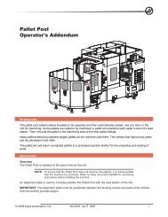
Mill Drill Rear Shipping Bracket Removal<br />
1. Remove the screws that secure the rear panel.<br />
2. Remove the four screws that hold the shipping bracket to the spindle and saddle castings.<br />
3. Remove the rear shipping bracket and two column shipping brackets (there are three bolts in each one)<br />
and replace the rear panel.<br />
MDC Pendant Arm Shipping Bracket Removal<br />
1. Remove the pendant shipping bracket, there are three screws holding it in place.<br />
2. Replace the pendant stop; orient it as shown in the illustration. Use the screws removed from the shipping<br />
bracket.<br />
poweR on<br />
Pendant<br />
Stop<br />
Pendant Stop<br />
(Rotated 180 )<br />
Existing Screw<br />
Existing<br />
Screws<br />
Shipping<br />
Bracket<br />
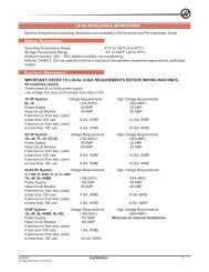
1. With the main switch on the electrical panel set to ON, press and release POWER ON at the upper left<br />
of the control panel. You will hear a click in the back of the machine and the fans will energize. After a few<br />
seconds, the display will appear on the screen.<br />
2. Press and release SETNG/GRAPH. Page down to the last page (press and release PAGE DOWN several<br />
times). Cursor to Setting 53, JOG W/O ZERO RETURN (with the cursor down key). Press and release the<br />
cursor right key and then press and release the WRITE key to turn this setting on. Turning on JOG W/O<br />
ZERO RETURN bypasses the zero return interlock.<br />
3. Press and release the RESET button twice, or until there are no alarms, to turn the servos on. (The<br />
message “ALARM” appears at the lower right of the screen if any alarms are in effect.)<br />
NOTE: If any alarms are present and cannot be cleared with the RESET button, press and<br />
release the ALARM / MESGS button for more information on the alarms. If you are<br />
unable to clear the alarms, write down the alarm numbers and call the factory.<br />
4. Press and release the HANDLE JOG button and check the screen for the “JOGGING Z AXIS HANDLE<br />
.001” message. If the message does not read .001, press and release the .001 button next to the HANDLE<br />
JOG button. If the "JOGGING__" message shows the X- or Y-axis instead of Z, press and release the +Z<br />
button. Verify that the head will travel SLOWLY (not more than 0.001 inch per impulse — the ".001" part of<br />
the Z-axis message). Jog the Z-axis to the top of its travel. For the VF-1/2/3/4, jog the Z-axis to the top of its<br />
travel, and remove the flex tube cradle as shown.<br />
18 Installation 96-0284A<br />
© <strong>Haas</strong> <strong>Automation</strong> June 2010