shot peening residual stress - Metal Improvement Company
shot peening residual stress - Metal Improvement Company
shot peening residual stress - Metal Improvement Company

Create successful ePaper yourself
Turn your PDF publications into a flip-book with our unique Google optimized e-Paper software.
C H A P T E R F O U R<br />
BENDING FA T IGUE<br />
22<br />
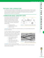
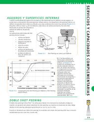
disruption of the tooth flank surface.<br />
The amount of compressive <strong>stress</strong> will<br />
be ~ 50% of that which hard <strong>shot</strong> will<br />
induce.<br />
The optimal way to induce resistance<br />
to pitting fatigue near the gear tooth<br />
pitch line is to induce a compressive<br />
<strong>stress</strong> followed by a lapping, honing, or<br />
isotropic finishing process. Care must<br />
be taken to not remove more than 10%<br />
of the <strong>shot</strong> <strong>peening</strong> layer. Processes<br />
that refine the surface finish of <strong>shot</strong><br />
<strong>peening</strong> dimples allow the contact load<br />
Figure 4-4 Typical Carburized Gear Residual Stress Profile<br />
to be distributed over a larger surface area reducing contact <strong>stress</strong>es.<br />
<strong>Metal</strong> <strong>Improvement</strong> Co. offers a <strong>shot</strong> <strong>peening</strong> and superfinishing process called C.A.S.E. SM that has increased<br />
pitting fatigue resistance of gears by 500%. Please see Chapter 11 for additional information and photomicrographs<br />
on this process.<br />
Increases in fatigue strength of 30% or more at 1,000,000 cycles are common in certain gearing<br />
applications. The following organizations/specifications allow for increases in tooth bending loads when<br />
controlled <strong>shot</strong> <strong>peening</strong> is implemented.<br />
• Lloyds Register of Shipping: 20% increase [Ref 4.2]<br />
• Det Norske Veritas: 20% increase [Ref 4.3]<br />
• ANSI/AGMA 6032-A94 Marine Gearing Specification: 15% increase<br />
C O N N E C T I N G R O D S<br />
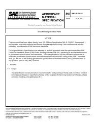
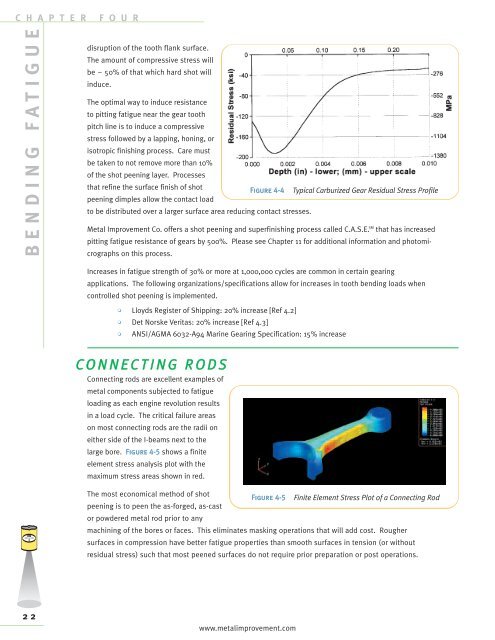
Connecting rods are excellent examples of<br />
metal components subjected to fatigue<br />
loading as each engine revolution results<br />
in a load cycle. The critical failure areas<br />
on most connecting rods are the radii on<br />
either side of the I-beams next to the<br />
large bore. Figure 4-5 shows a finite<br />
element <strong>stress</strong> analysis plot with the<br />
maximum <strong>stress</strong> areas shown in red.<br />
The most economical method of <strong>shot</strong><br />
<strong>peening</strong> is to peen the as-forged, as-cast<br />
or powdered metal rod prior to any<br />
Figure 4-5 Finite Element Stress Plot of a Connecting Rod<br />
machining of the bores or faces. This eliminates masking operations that will add cost. Rougher<br />
surfaces in compression have better fatigue properties than smooth surfaces in tension (or without<br />
<strong>residual</strong> <strong>stress</strong>) such that most peened surfaces do not require prior preparation or post operations.<br />
www.metalimprovement.com