shot peening residual stress - Metal Improvement Company
shot peening residual stress - Metal Improvement Company
shot peening residual stress - Metal Improvement Company

Create successful ePaper yourself
Turn your PDF publications into a flip-book with our unique Google optimized e-Paper software.
C H A P T E R T W E L V E<br />
C ONTROLL ING THE PROCESS<br />
48<br />
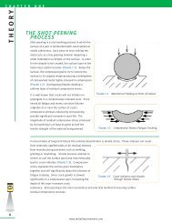
PEENSCAN ® (Coverage Verification): Determination of <strong>shot</strong> <strong>peening</strong> coverage can be fairly easy when<br />
softer materials have been peened as the dimples are quite visible. A 10-power (10x) magnifying glass is<br />
more than adequate for these conditions. In many applications determination of coverage is more<br />
difficult. Internal bores, tight radii, extremely hard materials, and large surface areas present additional<br />
challenges in determining coverage.<br />
<strong>Metal</strong> <strong>Improvement</strong> <strong>Company</strong> has developed the PEENSCAN ® process using DYESCAN ® fluorescent tracer<br />
dyes for this reason. PEENSCAN ® is ideal for measuring uniformity and extent of coverage for difficult<br />
conditions. The whitish-green dye is not visible under normal lighting conditions and must be viewed under<br />
a UV (black) light.<br />
The coating can be applied by dipping,<br />
brushing, or spraying the part under analysis.<br />
As the coated surface is impacted with <strong>peening</strong><br />
media, the impacts remove the fluorescent,<br />
elastic coating at a rate proportional to the<br />
actual coverage rate. When the part is viewed<br />
again under black light non-uniform coverage is<br />
visibly evident. The <strong>shot</strong> <strong>peening</strong> process<br />
parameters can then be adjusted until the<br />
PEENSCAN ® procedure verifies complete<br />
obliteration of the area of concern.<br />
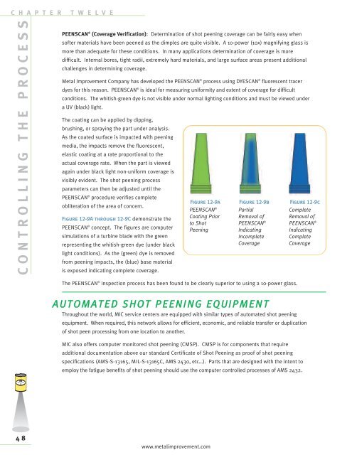
Figure 12-9A through 12-9C demonstrate the<br />
PEENSCAN ® concept. The figures are computer<br />
simulations of a turbine blade with the green<br />
representing the whitish-green dye (under black<br />
light conditions). As the (green) dye is removed<br />
from <strong>peening</strong> impacts, the (blue) base material<br />
is exposed indicating complete coverage.<br />
Figure 12-9a<br />
PEENSCAN ®<br />
Coating Prior<br />
to Shot<br />
Peening<br />
The PEENSCAN ® inspection process has been found to be clearly superior to using a 10-power glass.<br />
A U TOMATED S H OT P E E N I N G E Q UIPMENT<br />
Throughout the world, MIC service centers are equipped with similar types of automated <strong>shot</strong> <strong>peening</strong><br />
equipment. When required, this network allows for efficient, economic, and reliable transfer or duplication<br />
of <strong>shot</strong> peen processing from one location to another.<br />
MIC also offers computer monitored <strong>shot</strong> <strong>peening</strong> (CMSP). CMSP is for components that require<br />
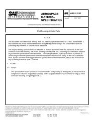
additional documentation above our standard Certificate of Shot Peening as proof of <strong>shot</strong> <strong>peening</strong><br />
specifications (AMS-S-13165, MIL-S-13165C, AMS 2430, etc…). Parts that are designed with the intent to<br />
employ the fatigue benefits of <strong>shot</strong> <strong>peening</strong> should use the computer controlled processes of AMS 2432.<br />
www.metalimprovement.com<br />
Figure 12-9b<br />
Partial<br />
Removal of<br />
PEENSCAN ®<br />
Indicating<br />
Incomplete<br />
Coverage<br />
Figure 12-9c<br />
Complete<br />
Removal of<br />
PEENSCAN ®<br />
Indicating<br />
Complete<br />
Coverage