Bulletin 2/2010 - Siempelkamp NIS
Bulletin 2/2010 - Siempelkamp NIS
Bulletin 2/2010 - Siempelkamp NIS

You also want an ePaper? Increase the reach of your titles
YUMPU automatically turns print PDFs into web optimized ePapers that Google loves.
SIEMPELKAMP | FOUNDRY/MACHINERY AND PLANTS 64 65<br />
For Alcoa, <strong>Siempelkamp</strong> is a well-known<br />
and trusted partner. <strong>Siempelkamp</strong> has<br />
developed and built several forging presses<br />
for Alcoa in the past. Both companies<br />
can look back on a relationship of mutual<br />
trust.<br />
Among other parts, the scope of supply<br />
for Alcoa consisted of 14 large cast parts<br />
for the upper, cross and lower beams as<br />
well as the foundation beams. For the<br />
manufacturing of these replacement<br />
parts, Alcoa had given three requirements:<br />
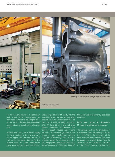
Machining with two portals<br />
Each new part had to fi t exactly into the<br />
available space of the part to be replaced<br />
and the connecting dimensions had to be<br />
the same, it could not weigh more than<br />
247.5 US tons (224.5 t), and had to be<br />
fatigue endurable. Furthermore, the<br />
scope of supply included custom parts<br />
such as a 105 t die change plate, a 45 t<br />
protection plate, miscellaneous centering<br />
rings and stroke-limiting collars as well as<br />
a guiding system for the cross beam. The<br />
die change plate consisted of three metal<br />
slabs (3,000 mm x 3,750 mm x 550 mm)<br />
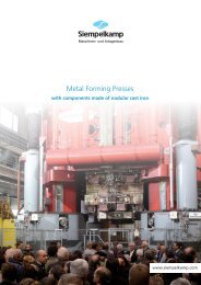
Machining on the large portal milling machine at <strong>Siempelkamp</strong><br />
that were welded together by electroslag<br />
remelting.<br />
From blue prints to simulation:<br />
50 years of engineering innovation<br />
The starting point for the production of<br />
the new cast parts were blue prints from<br />
the 1950s. Within the framework of the<br />
order, <strong>Siempelkamp</strong> used these blue prints<br />
to analyze the original design from the<br />
1950s, carried out calculations according<br />
to the Finite Element Method and