- Page 1 and 2:
IPC@CHIP Documentation index - SC12
- Page 3 and 4:
available from the download area of
- Page 5 and 6:
IPC@CHIP Documentation Index Introd
- Page 7 and 8:
1. Timer procedures must be impleme
- Page 9 and 10:
Top of list Index page Usage of the
- Page 11 and 12:
Top of list Index page Using Hardwa
- Page 13 and 14:
Top of list Index page 3. Since @CH
- Page 15 and 16:
Top of list Index page End of docum
- Page 17 and 18:
IPC@CHIP Documentation Index COMMAN
- Page 19 and 20:
Index page TYPE file Type a file. T
- Page 21 and 22:
Example rd temp Top of list Index p
- Page 23 and 24:
Top of list Index page ALE Enable/d
- Page 25 and 26:
Related Topics Top of list Index pa
- Page 27 and 28:
Top of list Index page Initial BATC
- Page 29 and 30:
Comments Example Make sure that oth
- Page 31 and 32:
Comments Top of list Index page tas
- Page 33 and 34:
CHIP.INI Documentation - SC12 @CHIP
- Page 35 and 36:
STDIO ● SERIAL_EXT_DMA ● SERIAL
- Page 37 and 38:
The new mode is shown on the consol
- Page 39 and 40:
Top of list Index page IP ADD_DEFAU
- Page 41 and 42:
Top of list Index page [PPPCLIENT]
- Page 43 and 44:
Example: REMOTEADDRESS=192.168.205.
- Page 45 and 46:
IDLETIME=500 By default, PPP server
- Page 47 and 48:
Top of list Index page PPP server c
- Page 49 and 50:
Comments Example: INITRETRIES0=2 Th
- Page 51 and 52:
[PPPSERVER] CTRLTIMEOUTx=timeout in
- Page 53 and 54:
PPPSERVER [PPPSERVER] HANGUPANSWERx
- Page 55 and 56:
Top of list Index page PPPSERVER [P
- Page 57 and 58:
Example: Top of list Index page FTP
- Page 59 and 60:
Top of list Index page FTP PASSWORD
- Page 61 and 62:
WEB [WEB] TEMPPATH=Name of a tempor
- Page 63 and 64:
Top of list Index page WEB The cons
- Page 65 and 66:
WEB [WEB] SEC_PASSWORDx=Define a pa
- Page 67 and 68:
USERx=user Comments Top of list Ind
- Page 69 and 70:
TRACE [TRACE] INTNOTSUPP=0/1 Commen
- Page 71 and 72:
Top of list Index page SERIAL [SERI
- Page 73 and 74:
MEMGAP=Paragraphs Comments Sets a m
- Page 75 and 76:
IPC@CHIP Documentation Index CONFIG
- Page 77 and 78:
● Interrupt_0xA0_function_0x19:_C
- Page 79 and 80:
Top of list Index page AX = 0. (Thi
- Page 81 and 82:
Comments Top of list Index page DI
- Page 83 and 84:
ES:DX Pointer to a 16 byte memory a
- Page 85 and 86:
Index page Interrupt 0xA0 service 0
- Page 87 and 88:
Parameters AH Must be 0x15 Return V
- Page 89 and 90:
AH ES:DI Comments Must be 0x20. Add
- Page 91 and 92:
int iniPutString(char *sectionName,
- Page 93 and 94:
Get the IPC@CHIP device names Param
- Page 95 and 96:
Return Value Comments AL= 1 DX=0: S
- Page 97 and 98:
Parameters AH AL BX Must be 0x33. B
- Page 99 and 100:
void huge my_putstr(char * pch, int
- Page 101 and 102:
Index page Interrupt 0xA0 service 0
- Page 103 and 104:
Parameters AH ES:DX Top of list Ind
- Page 105 and 106:
● Interrupt_0xAC_function_0x0B:_A
- Page 107 and 108:
Socket descriptor Return Value DX =
- Page 109 and 110:
put into the buffer. The sender can
- Page 111 and 112:
The application sleeps for a specif
- Page 113 and 114:
Top of list Index page Interrupt 0x
- Page 115 and 116:
for the API_SEND function (or recv_
- Page 117 and 118:
a new connection. Related Topics To
- Page 119 and 120:
AH BX ES:DI 0x16 (= API_SETSOCKOPT)
- Page 121 and 122:
Interrupt 0xAC service 0x19: API_RE
- Page 123 and 124:
Related Topics Top of list Index pa
- Page 125 and 126:
SocketInfo s[64]; int avail, i; ava
- Page 127 and 128:
Comments AX = -2 (=API_NOT_SUPPORTE
- Page 129 and 130:
Tests if PPP server is available in
- Page 131 and 132:
Index page Interrupt 0xAC service 0
- Page 133 and 134:
DS:SI CX 6 Get pointer to AtEntry d
- Page 135 and 136:
Bits of AX and DX contains the requ
- Page 137 and 138:
Parameters AH 0x74 (= TCPIP_STATIST
- Page 139 and 140:
Structure at [ES:DI] is filled with
- Page 141 and 142:
Parameters AH ES:DI 0x7A (= IP_USER
- Page 143 and 144:
This function is used to delete the
- Page 145 and 146:
Related Topics Top of list Index pa
- Page 147 and 148:
CX Number of data structures in arr
- Page 149 and 150:
DS:SI Output Parameter: Pointer to
- Page 151 and 152:
For more detailed description see H
- Page 153 and 154:
BX CX ES:DI Number of available rec
- Page 155 and 156:
Related Topics Top of list Index pa
- Page 157 and 158:
IPC@CHIP Documentation Index TCP/IP
- Page 159 and 160:
TCP/IP Application Developers Note
- Page 161 and 162:
ArpHeader Address Resolution Protoc
- Page 163 and 164:
Top of list Index page This buffer
- Page 165 and 166:
Comments This data structure and sp
- Page 167 and 168:
Comments These structures are only
- Page 169 and 170:
Comments unsigned long ipReasmOKs;
- Page 171 and 172:
typedef struct tag_ping_command { i
- Page 173 and 174:
The PPPDial structure is used durin
- Page 175 and 176:
Related Topics ❍ optionName=PPP_I
- Page 177 and 178:
SetSocketOption Comments This data
- Page 179 and 180:
Top of list Index page UdpMib Comme
- Page 181 and 182:
Programming client server applicati
- Page 183 and 184:
RTOS API - SC12 @CHIP-RTOS V1.10 IP
- Page 185 and 186:
AH BX 0 (=RTX_SLEEP_TIME) Sleep tim
- Page 187 and 188:
Top of list Index page Interrupt 0x
- Page 189 and 190:
Return Value Comments DX=0 (always
- Page 191 and 192:
An out of range priority value (CX)
- Page 193 and 194:
Comments DX!=0 failure AX: contains
- Page 195 and 196:
BX ES:DI 0x19 (= RTX_RESERVE_RES) I
- Page 197 and 198:
Top of list Index page RTX_GET_SEM
- Page 199 and 200:
BX:SI Output Parameter: Pointer to
- Page 201 and 202:
ES:DI CX Output Parameter: Pointer
- Page 203 and 204:
Comments DX!=0 failure AX: contains
- Page 205 and 206:
The task name is not a null termina
- Page 207 and 208:
Top of list Index page Interrupt 0x
- Page 209 and 210:
AH BX ES:DI DS:SI 0x40 (= RTX_CREAT
- Page 211 and 212:
Interrupt 0xAD service 0x43: RTX_WA
- Page 213 and 214:
ES:DI 0x46 (= RTX_FIND_EVENTGROUP)
- Page 215 and 216:
ES:DI Pointer to a 12 byte message
- Page 217 and 218:
Interrupt 0xAD service 0x55: RTX_FI
- Page 219 and 220:
Multitasking with @Chip-RTOS Some c
- Page 221 and 222:
ackground data base search in the e
- Page 223 and 224:
Suspended Free to run RTX_Resume_Ta
- Page 225 and 226:
Figure 1 ) Sleep Based Periodic Loo
- Page 227 and 228:
can potentially interrupt execution
- Page 229 and 230:
} } Figure 5 ) Protected Critical S
- Page 231 and 232:
RTOS Overview - SC12 @CHIP-RTOS V1.
- Page 233 and 234:
Time / Date Services The following
- Page 235 and 236:
Top of list Index page is willing t
- Page 237 and 238: system's maximum number of availabl
- Page 239 and 240: Prior to making the RTX_TASK_CREATE
- Page 241 and 242: B4: Message Exchange wait B5: -- no
- Page 243 and 244: name or void huge MyTimerProc(unsig
- Page 245 and 246: IPC@CHIP Documentation Index @CHIP-
- Page 247 and 248: RTOS Application Developers Note -
- Page 249 and 250: DOS Interface Documentation - SC12
- Page 251 and 252: Parameters AH DL 0x02 Character to
- Page 253 and 254: AH 0x08 Return Value Comments Retur
- Page 255 and 256: AH 0x19 Return Value AL = drive whe
- Page 257 and 258: Top of list Index page Interrupt 0x
- Page 259 and 260: Only ten DTA entries for user tasks
- Page 261 and 262: Note: Top of list Index page In @CH
- Page 263 and 264: Parameters AH CX 0x3C File attribut
- Page 265 and 266: Top of list Index page Interrupt 0x
- Page 267 and 268: Top of list Index page Get/Set File
- Page 269 and 270: BX DX Handle Device data Return Val
- Page 271 and 272: A paragraph is 16 bytes in length.
- Page 273 and 274: Comments Top of list Index page AX
- Page 275 and 276: operations such as renaming, moving
- Page 277 and 278: AL BX CX DX AL=0 to get the date an
- Page 279 and 280: Top of list Index page Interrupt 0x
- Page 281 and 282: Hardware API - SC12 @CHIP-RTOS V1.1
- Page 283 and 284: Top of list Index page if ALE is us
- Page 285 and 286: Top of list Index page Interrupt 0x
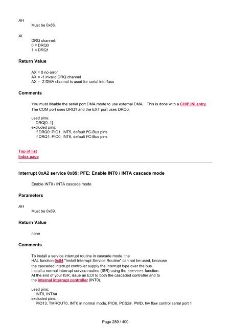
- Page 287: Comments If on a given timer the ex
- Page 291 and 292: AH ES:DI Must be 0x90. Pointer to a
- Page 293 and 294: Comments 8 Bit data in ax, ax = (da
- Page 295 and 296: Parameters AH DX BX CX Must be 0x83
- Page 297 and 298: Top of list Index page RTX_SIGNAL_E
- Page 299 and 300: none Related Topics Top of list Ind
- Page 301 and 302: Top of list Index page Interrupt 0x
- Page 303 and 304: Related Topics Top of list Index pa
- Page 305 and 306: instead be the frequency reported b
- Page 307 and 308: Return Value none Comments Top of l
- Page 309 and 310: Starts the DMA mode. After calling
- Page 311 and 312: BX:SI ES:DI 1 = DRQ1 Output Paramet
- Page 313 and 314: Return Value none Comments Call thi
- Page 315 and 316: Hardware API Layers - SC12 @CHIP-RT
- Page 317 and 318: This function initializes the I2C b
- Page 319 and 320: AL CX Slave address, LSB:0 => Trans
- Page 321 and 322: AH AL 0x8F PIO pin number, [0..13]
- Page 323 and 324: AH ES:DI CX Must be 0x96 Pointer to
- Page 325 and 326: I2C Bus and SPI API Updates - SC12
- Page 327 and 328: ● Interrupt_0x14_function_0x04:_I
- Page 329 and 330: DX Port number: 0 for EXT, 1 for CO
- Page 331 and 332: DX 0x08 Port number: 0 for EXT, 1 f
- Page 333 and 334: AH AL DX 0x0F Bit mask describing r
- Page 335 and 336: ES:DI Pointer to user buffer. Retur
- Page 337 and 338: Top of list Index page transmitter.
- Page 339 and 340:
DX 2: short break (1 frame) 3: extr
- Page 341 and 342:
Top of list Index page send queue.
- Page 343 and 344:
User specific TCPIP Device driver -
- Page 345 and 346:
Generic example: int huge myDevSend
- Page 347 and 348:
Implementation of this function is
- Page 349 and 350:
} } Related Topics Top of list Inde
- Page 351 and 352:
{ result= Dev_Wait_DHCP_Complete(&m
- Page 353 and 354:
Index page Configuring the PPP Serv
- Page 355 and 356:
the call without waiting for the PP
- Page 357 and 358:
Top of list Index page Available Ex
- Page 359 and 360:
● Interrupt_0xAB_function_0x07:_C
- Page 361 and 362:
Return Value Comments DX =0 success
- Page 363 and 364:
Top of list Index page CGI_FINDNEXT
- Page 365 and 366:
IPC@CHIP Documentation Index CGI AP
- Page 367 and 368:
Top of list Index page @CHIP V0.92
- Page 369 and 370:
IPC@CHIP Documentation Index Data S
- Page 371 and 372:
Comments typedef struct { //*******
- Page 373 and 374:
IPC@CHIP Documentation Index CGI AP
- Page 375 and 376:
CGI Examples Available - SC12 @CHIP
- Page 377 and 378:
The interrupt declaration will moti
- Page 379 and 380:
Interrupt 0xAE service 0x01: DRIVER
- Page 381 and 382:
Handle from ACCESS_TYPE call 0x02 R
- Page 383 and 384:
AH 0x15 Return Value Carry flag:0,
- Page 385 and 386:
Top of list Index page ACCESS_TYPE
- Page 387 and 388:
Interrupt 0xB0 service 0x02: Deinst
- Page 389 and 390:
HW API handler latency RTX handler
- Page 391 and 392:
Scalable @CHIP-RTOS variants for th
- Page 393 and 394:
IPC@CHIP Documentation Index Progra
- Page 395 and 396:
IPC@CHIP Documentation Index Introd
- Page 397 and 398:
Top of list Index page TFTP server
- Page 399 and 400:
Top of list Index page Possible err


