HARBOR SYSTEM MASTER PLAN - City and Borough of Sitka
HARBOR SYSTEM MASTER PLAN - City and Borough of Sitka
HARBOR SYSTEM MASTER PLAN - City and Borough of Sitka

You also want an ePaper? Increase the reach of your titles
YUMPU automatically turns print PDFs into web optimized ePapers that Google loves.
With the above noted damage, the service life <strong>of</strong> the components is reduced to 20 years, or less. The<br />
power <strong>and</strong> lighting systems require substantial rehabilitation within the next five years.<br />
Also note that the “Marine & Boatyard” shore-tie pedestals utilize digital revenue meters. Again, the<br />
CBS Electric Department prefers Form 1S meters as noted previously in the Findings for Thompson<br />
Harbor. And note that the lighting on the pedestrian gangway is damaged, leaving the gangway with an<br />
inadequate amount <strong>of</strong> illumination.<br />
Crescent Harbor<br />
<strong>Sitka</strong> Harbor System Master Plan<br />
Condition Inventory<br />
Existing Systems<br />
The electrical systems at Crescent Harbor<br />
consist <strong>of</strong> power distribution, shore-tie<br />
pedestals, <strong>and</strong> lighting. Power is provided<br />
for most <strong>of</strong> the vessels with illumination<br />
<strong>of</strong> all <strong>of</strong> the facility. Communication l<strong>and</strong><br />
lines provide telephone to vessels where<br />
requested. These electrical systems were<br />
installed when the electrical systems were<br />
renovated in 2005.<br />
Power Distribution System:<br />
The power for the Crescent Harbor is<br />
provided from two locations along<br />
Lincoln Avenue. One utility service is<br />
positioned to route power down the<br />
gangway at Finger Float No. 2 <strong>and</strong><br />
distribute to Finger Float Nos. 1, 2, 3, &<br />
4, as well as the main float. Power from the second utility service is routed down the gangway at Finger<br />
Float No. 4, distributing to Finger Float Nos. 5 through 7. The feeders to the floating docks are all<br />
protected by circuit breakers mounted in panel boards near to the approach end <strong>of</strong> the gangways. There<br />
are no utility revenue meters at the service circuit breakers.<br />
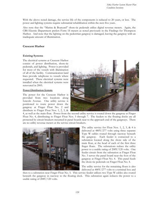
The utility service for Float Nos. 1, 2, 3, & 4 is<br />
delivered at 480Y/277 volts using three separate<br />
Type W cables routed through raceway beneath<br />
the gangway. Each feeder is connected to a<br />
substation located along the shore side <strong>of</strong> the<br />
main float, at the head <strong>of</strong> each <strong>of</strong> the first three<br />
finger floats. The substations reduce the utility<br />
power to a usable rating <strong>of</strong> 208Y/120 volts. One<br />
feeder circuit from the substation at Finger Float<br />
No. 3 serves the panel board near the foot <strong>of</strong> the<br />
gangway at Finger Float No. 4. This panel feeds<br />
the shore-tie pedestals on Finger Float No. 4.<br />
The utility service for the remaining floats is also<br />
delivered at 480Y/277 volts to a terminal box <strong>and</strong><br />
then to a substation near Finger Float No. 5. This service feeder utilizes two Type W cables also routed<br />
beneath the gangway in raceway to the floating dock. This substation again reduces the power to a<br />
usable rating <strong>of</strong> 208Y/120 volts.<br />
120