ERCOFTAC Bulletin - Centre Acoustique
ERCOFTAC Bulletin - Centre Acoustique
ERCOFTAC Bulletin - Centre Acoustique

Create successful ePaper yourself
Turn your PDF publications into a flip-book with our unique Google optimized e-Paper software.
Numerical and Experimental Characterization of Fan<br />
Noise Installation Effects<br />
1 Introduction<br />
D.-C. Mincu 1 and E. Manoha 1<br />
1 ONERA–The French Aerospace Lab, F-92322, Chatillon, France<br />
After decades of continuous reduction of the noise radiated<br />
by aeronautic powerplant systems, and especially<br />
by modern turbofans with high by-pass ratio, further<br />
improvements are now expected from engine installation<br />
effects, which means by using the airframe (fuselage,<br />
wing, empennage), or even the nacelle itself, as<br />
noise shielding surfaces through innovative engine integrations.<br />
Current acoustic studies of innovative engine<br />
installations rely on combining numerical predictions and<br />
experiments, mostly at model scale. Moreover, the development<br />
of innovative numerical methods must rely on<br />
dedicated experimental database achieved on academic<br />
configurations for validation. This was the case, for example,<br />
in the European project NACRE (New Aircraft<br />
Concepts Research in Europe, 2005-2010) where Airbus<br />
recently led studies of the RFN concept [1] (Rear Fuselage<br />
Nacelle, see Figure 1, middle) combining (i) experiments<br />
in Onera’s CEPRA19 aeroacoustic open-jet windtunnel<br />
and (ii) several up-to-date numerical prediction<br />
methods for isolated/installed jet and fan noise from a<br />
turbofan engine. In the case of the Payload Driven Aircraft<br />
(PDA) or “flying wing“ configuration [2] (Figure 1,<br />
left), also studied in NACRE (Task 3.2 “Radical Engine<br />
Integration“ coordinated by Onera), radical solutions<br />
were tested with the engine installed as close as<br />
possible to the airframe, or even partly buried inside,<br />
following interests expressed by the airframer (reduced<br />
pitching moment, weight, and noise).<br />
Although less revolutionary, the nacelle itself can be<br />
used to generate acoustic installation effects on fan noise,<br />
as it is already the case for nacelles with scarfed air inlet,<br />
a concept which is assumed to deviate the fan noise propagation<br />
in the upward direction. Within the European<br />
project OPENAIR (OPtimisation for low Environmental<br />
Noise impact AIRcraft), ”scarfing” (SAF) concept is<br />
tentatively applied to the downstream nozzle of the turbofan<br />
(Figure 1, right), with the objective to decrease<br />
fan noise levels radiated towards the ground through the<br />
turbofan nozzle [3].<br />
However, major issues can occur from these types<br />
of installations, for example (i) problems of ”fatigue”<br />
structure may arise in the RFN concept, (ii) for the<br />
scarfed configuration, the thrust axis may be deviated<br />
and the mass-flow affected and (iii) for a semi-buried<br />
engine, the proximity of the airframe surface may<br />
result in a strong distortion of the intake flow and, for<br />
extreme configurations, the possible ingestion of the<br />
thick airframe boundary layer may occur. In addition,<br />
certification issues can become critical, especially for the<br />
case of engine burst event and, for this purpose, material<br />
and energy absorption analysis must be considered.<br />
The numerical prediction of engine acoustic installation<br />
effects is very complex because it requires combining<br />
(a) the simulation of the noise generation by the engine<br />
and the near field acoustic propagation of this noise<br />
in a complex flow, and (b) the acoustic scattering on<br />
the aircraft surface and propagation up to the observer<br />
and, finally, the possible strong coupling between (a)<br />
and (b), through the retroaction of the acoustic field<br />
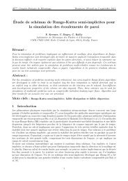
on the noise generation mechanisms. One possible<br />
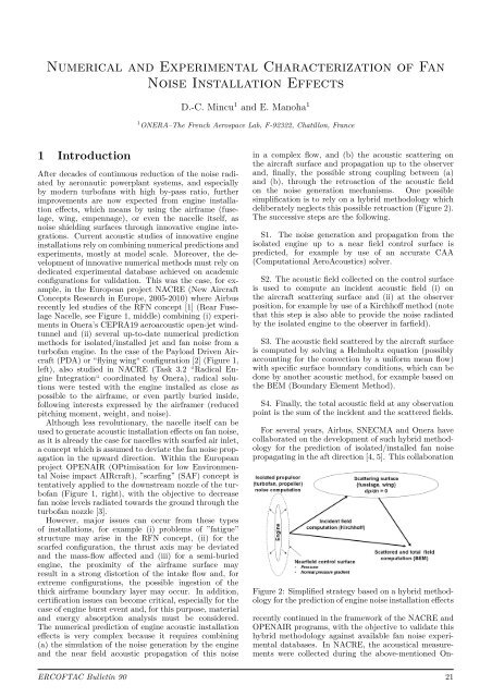
simplification is to rely on a hybrid methodology which<br />
deliberately neglects this possible retroaction (Figure 2).<br />
The successive steps are the following.<br />
S1. The noise generation and propagation from the<br />
isolated engine up to a near field control surface is<br />
predicted, for example by use of an accurate CAA<br />
(Computational AeroAcoustics) solver.<br />
S2. The acoustic field collected on the control surface<br />
is used to compute an incident acoustic field (i) on<br />
the aircraft scattering surface and (ii) at the observer<br />
position, for example by use of a Kirchhoff method (note<br />
that this step is also able to provide the noise radiated<br />
by the isolated engine to the observer in farfield).<br />
S3. The acoustic field scattered by the aircraft surface<br />
is computed by solving a Helmholtz equation (possibly<br />
accounting for the convection by a uniform mean flow)<br />
with specific surface boundary conditions, which can be<br />
done by another acoustic method, for example based on<br />
the BEM (Boundary Element Method).<br />
S4. Finally, the total acoustic field at any observation<br />
point is the sum of the incident and the scattered fields.<br />
For several years, Airbus, SNECMA and Onera have<br />
collaborated on the development of such hybrid methodology<br />
for the prediction of isolated/installed fan noise<br />
propagating in the aft direction [4, 5]. This collaboration<br />
Figure 2: Simplified strategy based on a hybrid methodology<br />
for the prediction of engine noise installation effects<br />
recently continued in the framework of the NACRE and<br />
OPENAIR programs, with the objective to validate this<br />
hybrid methodology against available fan noise experimental<br />
databases. In NACRE, the acoustical measurements<br />
were collected during the above-mentioned On-<br />
<strong>ERCOFTAC</strong> <strong>Bulletin</strong> 90 21