ERCOFTAC Bulletin - Centre Acoustique
ERCOFTAC Bulletin - Centre Acoustique
ERCOFTAC Bulletin - Centre Acoustique

You also want an ePaper? Increase the reach of your titles
YUMPU automatically turns print PDFs into web optimized ePapers that Google loves.
2 Coupled simulations<br />
A key problem with LES is that inflow and outflow conditions,<br />
generally, must be correctly characterized. At<br />
inflow boundaries, turbulence must be prescribed that<br />
has temporal and spatial scales, which are correctly correlated,<br />
and representative of the flow in the actual system.<br />
At outflow, for a turbomachine, for example, the<br />
need goes beyond simply preventing reflections. For example,<br />
a downstream axial compressor redistributes flow<br />
and hence has a strong upstream impact. Similarly, upstream<br />
rotors have a strong downstream influence. Turbomachines<br />
are highly coupled systems. Hence, the specification<br />
of inflow and outflow ”boundary conditions”<br />
presents challenges.<br />
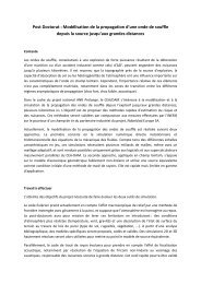
Figure 4: Surface conforming octree grid from Xia et al.<br />
[26]<br />
An approach to overcome this and create coupling is<br />
to represent upstream and downstream turbomachinery<br />
elements using low order models. For example, body<br />
forces can be used to replicate the turning and total<br />
temperature and pressure distributions. These can be<br />
utilized in a multi-fidelity approach. For example in [27]<br />
body forces [28] are used to generate the flow turning<br />
and axial mass flux induced by an upstream rotor in an<br />
open rotor engine and also the influence of a downstream<br />
compressor. The rotor model was also adapted to replicate<br />
unsteady wakes with controlled momentum deficits,<br />
turbulence length scales and intensities. The wakes are<br />
found to substantially influence the flow in the intake<br />
duct and the distortion levels at the compressor face.<br />
The use of azimuthally enhanced body force modeling<br />
for fan acoustics is also reported in Defoe et al. [29].<br />
In Eastwood [16] body forces are used to model wakes<br />
from upstream blade rows inside a jet nozzle. These<br />
wakes generate large scales eddies in the LES simulation.<br />
Much work has been conducted on isolated jets,<br />
the focus being on exploring noise from the propulsive<br />
jet in gas turbine engines. However, as shown in Xia<br />
et al. [30] and Eastwood et al. [31] the wing, flap, pylon,<br />
and internal jet geometry can substantially influence<br />
the development of the jet plume and acoustics. Hence,<br />
it seems future evolutions in acoustics modelling should<br />
encompass the following elements:<br />
• Multi fidelity modeling that accounts for the coupled<br />
nature of systems such as gas turbine engines<br />
and hence the challenges with regards to inflow and<br />
outflow boundary conditions – especially for LES;<br />
• Multi-objective simulations that enable the tensions<br />
between aerodynamic and aeroacoustic re-<br />
quirements to be explored and potential synergies<br />
between these elements and ultimately;<br />
• Multi-physics simulations.<br />
Again, in the multi-fidelity context accurately predicting<br />
aerodynamic and aeroacoustic behaviour can need<br />
coupled fluid-structure calculations. For example, with<br />
open rotor engines to accurately capture aerodynamics,<br />
blade rotor untwist needs to be captured [32]. In the hydroacoustics<br />
of marine propellers structural deflections<br />
are a key sound source component as is the multi-physics<br />
element of cavitation.<br />
2.1 Meshing and grid densities<br />
As we move to making large scale coupled simulations<br />
meshing presents a great challenge. Figures 2 and 3<br />
show meshes and simulations for recent large-scale coupled<br />
simulations for intakes of open rotor engines [27] and<br />
exhaust plumes [30]. Both present substantial acoustic<br />
challenges. In Figure 2, the first three frames give mesh<br />
views and the last frame contours of total pressure but<br />
for a coupled intake that has no bifurcation (see [27]).<br />
Figure 3 shows the block topology and contours of instantaneous<br />
axial velocity for a nozzle-pylon-wing-flap<br />
LES type calculation. The core flow is hot. The multiblock<br />
meshes used for these simulations give relatively<br />
high computational performance in terms of accuracy<br />
and cost for both computational acoustics and aerodynamics.<br />
However, they are tremendously time consuming<br />
to produce and need considerable skill. Work automating<br />
this process is ongoing [33] [34] [35]. For highly<br />
complex geometries, hexahedral rich octree meshes (see<br />
Figure 4), with surface conforming cells [26] offer solution<br />
accuracy but carry the computational overhead of<br />
an unstructured flow solver. On balance perhaps overset<br />
grids offer a good balance with regards to computational<br />
efficiency and mesh generation time scales [36] [37]. Naturally<br />
they are amenable to high order solutions.<br />
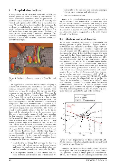
Figure 5: Grid requirements for LES and hybrid LES-<br />
RANS combined with typical grid densities actually used<br />
by various groups (from [38])<br />
Main gas path turbomachinery calculations the rotorstator<br />
pairs can have non-integer ratios of blade counts.<br />
This prevents the use of simple periodic boundary conditions.<br />
To overcome this problem adjustments in blade<br />
42 <strong>ERCOFTAC</strong> <strong>Bulletin</strong> 90