ERCOFTAC Bulletin - Centre Acoustique
ERCOFTAC Bulletin - Centre Acoustique
ERCOFTAC Bulletin - Centre Acoustique

Create successful ePaper yourself
Turn your PDF publications into a flip-book with our unique Google optimized e-Paper software.
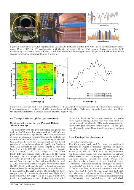
Figure 3: Views of the NACRE experiment in CEPRA 19. Left side: isolated TPS with the φ 5 m circular microphone<br />
array. Center: TPS in RFN configuration with the aircraft model. Right: Wall pressure fluctuations at the BPF<br />
measured by the internal array of Kulite transducers located inside the bypass duct. Upper side: RMS on each Kulite<br />
sensor. Lower side: azimuthal Fourier transform<br />
Figure 4: RMS sound field of the isolated/installed TPS, measured by the circular array of 48 microphones (diameter<br />
5 m, extrapolated to r = 6 m). Left side: azimuthal/axial distribution. Right side: cut in the flyover direction. Note:<br />
the internal bifurcation is located at the azimuthal angle 0 ◦ /360 ◦<br />
c) Computational global parameters<br />
Semi-buried engine for the Payload Driven<br />
Aircraft concept.<br />
The main entry data are grids containing the geometries<br />
and the RANS mean flows computed by ONERA’s Applied<br />
Aerodynamics Department. One of the objectives<br />
of these aerodynamic computations was to evaluate the<br />
influence of the "offset level", corresponding to the vertical<br />
distance between the fuselage level and the lowest<br />
position of the engine fan plane, divided by the fan diameter.<br />
Two different nacelle shapes (Figure 5, left) have<br />
been designed by ONERA with the offset level targets<br />
of 8 % (Shape 1) and 15 % (Shape 2). This “offset<br />
level“ difference induces slight differences in the upper<br />
lip shape. For both shapes the fan plane is located at<br />
x = 1.23R (where R is the fan radius or internal nacelle<br />
radius) from the inlet lip. For both nacelle shapes 1 and<br />
2, CAA structured multi-block grids were derived from<br />
the RANS grid with specific criteria based on homogeneous<br />
cell size depending on the acoustic wave length to<br />
be propagated. The grid is adapted to acoustic “in-flow”<br />
computations. In these cases, the considered flight Mach<br />
number is rather low (approach, M = 0.25), but the flow<br />
inside the nacelle can be much higher (up to M = 0.8<br />
in the fan plane), so the acoustic waves in the nacelle<br />
travel against strong adverse flow with very small apparent<br />
acoustic wavelength. This leads to considerably<br />
increase the grid resolution in this region. The final grid<br />
was obtained by using Gambit and contains 4.9 millions<br />
points.<br />
Rear Fuselage Nacelle concept<br />
a) CAA Computation<br />
The 3D acoustic mesh used for these computations is<br />
presented in Figure 5 (middle), showing the splitted<br />
blocks for parallel computing on 256 processors. The<br />
geometry of the aft TPS with its axisymmetrical<br />
non-homogenous mean flow was provided by Airbus.<br />
sAbrinA-V0 is used to compute the propagation of<br />
fan noise modes, through the nacelle bypass duct<br />
and the turbofan exhaust, up to a cylindrical control<br />
("Kirchhoff") surface surrounding the engine. In order to<br />
"acoustically" take into account the three-dimensionality<br />
of the by-pass duct, an internal bifurcation was added<br />
inside the duct between the fan plane and duct exit,<br />
with the same axial extent as in the actual TPS. For<br />
simplicity sake (the mean flow remains axisymmetrical),<br />
the bifurcation was modeled as a rigid wall (Wall<br />
<strong>ERCOFTAC</strong> <strong>Bulletin</strong> 90 23