ERCOFTAC Bulletin - Centre Acoustique
ERCOFTAC Bulletin - Centre Acoustique
ERCOFTAC Bulletin - Centre Acoustique

Create successful ePaper yourself
Turn your PDF publications into a flip-book with our unique Google optimized e-Paper software.
serrations to full size wind-turbine blades and found overall<br />
self-noise reductions of 2-3dB without adversely affecting<br />
aerodynamic performance. Nevertheless, the precise<br />
mechanism by which this noise reduction occurs is<br />
not yet fully understood. Understanding those mechanisms<br />
could lead to improvements in serration design,<br />
and possibly the development of alternative techniques<br />
based on similar physical principles. Our studies have<br />
therefore also aimed at numerically investigating the flow<br />
around airfoils with trailing edge modifications to identify<br />
the mechanism by which the noise reduction effect<br />
is achieved.<br />
Direct numerical simulation (DNS) is the preferred<br />
tool for such fundamental studies due to the absence of<br />
modelling. Compressible DNS allow an accurate representation<br />
of hydrodynamic phenomena such as turbulence<br />
and transition to turbulence, and of the propagation<br />
of acoustic waves. Conducting direct noise simulations<br />
avoids interfacing between solution methods as required<br />
for hybrid approaches, and allows for the presence<br />
of acoustic feed-back loops [15]. The complex geometries<br />
associated with trailing edge modifications represent<br />
a considerable numerical challenge using high-order<br />
accuracy spatial schemes. For this reason a purposely<br />
developed immersed boundary method representing the<br />
trailing edge modification has been employed.<br />
Governing equations<br />
Our in-house DNS code directly solves the unsteady,<br />
compressible Navier-Stokes equations, written in nondimensional<br />
form as<br />
ρ,t + (ρuk) ,k = 0 , (1)<br />
(ρui) ,t + [ρuiuk + pδik − τik] ,k = 0 , (2)<br />
(ρE) ,t + [uk (ρE + p) + qk − uiτik] ,k = 0 , (3)<br />
where the total energy is defined as E =<br />
T/ γ (γ − 1)M 2 + 0.5uiui. The stress tensor<br />
and the heat-flux vector are computed as<br />
τik = µ (ui,k + uk,i − 2/3uj,jδik) /Re<br />
qk = −µT,k/[(γ − 1)M 2 PrRe] , (4)<br />
respectively, where the Prandtl number is assumed to<br />
be constant at Pr = 0.72, and γ = 1.4. The molecular<br />
viscosity µ is computed using Sutherland’s law [16], setting<br />
the ratio of the Sutherland constant over freestream<br />
temperature to 0.36867. To close the system of equations,<br />
the pressure is obtained from the non-dimensional<br />
equation of state p = (ρT)/(γ M 2 ). The primitive variables<br />
ρ, ui, and T have been nondimensionalized by the<br />
freestream conditions and the airfoil chord is used as<br />
the reference length scale. Dimensionless parameters Re,<br />
Pr and M are defined using free-stream (reference) flow<br />
properties.<br />
Numerical method<br />
The finite-difference code used for the current investigation<br />
is based on a code extensively used for compressible<br />
turbulence research, such as compressible turbulent<br />
plane channel flow [17], or turbulent flow over<br />
a flat-plate trailing-edge [18]. The underlying numerical<br />
algorithm consists of a five-point fourth-order accurate<br />
central difference scheme combined with a fourthorder<br />
accurate Carpenter boundary scheme [19] for the<br />
spatial discretization, and an explicit fourth-order accurate<br />
Runge-Kutta scheme for time-stepping. No artificial<br />
viscosity or filtering is used. Instead, stability is<br />
enhanced by appropriate treatment of the viscous terms<br />
in combination with entropy splitting of the inviscid flux<br />
terms [17]. The code was extended so that it could be<br />
applied to a C-type grid with wake connection. At the<br />
freestream boundary, where the only disturbances likely<br />
to reach the boundary will be in the form of acoustic<br />
waves, an integral characteristic boundary condition is<br />
applied [20], in addition to a sponge layer comprising a<br />
dissipation term added to the governing equations. At<br />
the downstream exit boundary, which is subject to the<br />
passage of nonlinear amplitude fluid structures, a zonal<br />
characteristic boundary condition [21] is applied for increased<br />
effectiveness. At the airfoil surface an adiabatic,<br />
no slip condition is applied. This variant of the code<br />
has been recently used for direct numerical simulations<br />
of transitional flows on full airfoil configurations [15, 22].<br />
For simulations of airfoils with serrated and non-serrated<br />
flat-plate trailing-edge extensions an immersed boundary<br />
method (IBM), as described in Sandberg and Jones [23],<br />
was used.<br />
All simulations conducted used a C-type domain with<br />
dimensions of 5 chord-lengths from the trailing edge to<br />
the outflow boundary, 7.3 chord-lengths from the airfoil<br />
surface to the freestream boundary, and, in three<br />
dimensional cases, a spanwise width of 0.2 chords. The<br />
influence of domain size and grid resolution have been investigated<br />
thoroughly for the flow around a NACA-0012<br />
airfoil at Re = 5 × 10 4 and α = 5 ◦ in Jones et al.[22].<br />
At a chord-Reynolds number of Re = 5 × 10 4 , in the<br />
tangential direction, 2570 grid points were used, with<br />
1066 and 1126 points clustered over the airfoil for the<br />
cases without and with trailing edge extensions, respectively.<br />
In the lateral direction, 692 grid points were used<br />
and for fully turbulent flows the spanwise domain was<br />
discretized with 96 points [23]. For the investigation of<br />
acoustic feedback loops, the Reynolds number was specified<br />
at Re = 1 × 10 5 and the domain was discretized<br />
using 3122 tangential and 736 normal grid points [24].<br />
Results<br />
Acoustic feedback loop<br />
A study by Jones et al. [15] showed that in two dimensional<br />
simulations of flow over a NACA-0012 airfoil the<br />
vortex shedding frequency was considerably lower than<br />
that of the most unstable hydrodynamic instability obtained<br />
through linear stability analysis. Using a forced<br />
Navier–Stokes simulation approach, it was also shown<br />
that the time-averaged flow fields are globally unstable<br />
due to an acoustic feedback loop, while classical linear<br />
stability theory predicted no local absolute instability.<br />
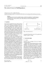
The acoustic feedback loop was shown to be composed<br />
of (A) instability waves convecting over the suction side<br />
of the airfoil, (B) an acoustic scattering at the trailing<br />
edge of the airfoil, (C) acoustic waves propagating upstream,<br />
and (D) a region of receptivity within boundary<br />
layer downstream of the leading edge, as illustrated<br />
in Figure (1). The preferred frequency of the acousticfeedback<br />
loop is significantly lower than that of the most<br />
convectively amplified instability wave and is comparable<br />
to that of the vortex shedding observed in two dimensions.<br />
It was therefore suggested that the acousticfeedback<br />
loop may play a role in frequency selection for<br />
the vortex shedding that occurs naturally.<br />
<strong>ERCOFTAC</strong> <strong>Bulletin</strong> 90 5