ES7000 Model 7600R G2 Installation and User's Guide
ES7000 Model 7600R G2 Installation and User's Guide
ES7000 Model 7600R G2 Installation and User's Guide

You also want an ePaper? Increase the reach of your titles
YUMPU automatically turns print PDFs into web optimized ePapers that Google loves.
The <strong>ES7000</strong> <strong>Model</strong> <strong>7600R</strong> <strong>G2</strong> Server<br />
Rear view<br />
- Link error LED: When this amber LED is lit, indicates that a QPI link fault or a<br />
EXA link fault has occurred. The port LED for the link that has been disconnected<br />
will not be lit on the rear of the Memory Expansion Module. EXA link LEDs are on<br />
the rear of the Memory Expansion Module, <strong>and</strong> the QPI link LEDs are on the<br />
server to which the memory drawer expansion is connected.<br />
- Fan error LED: When this amber LED is lit, it indicates a fan error.<br />
- System board error LED: When this amber LED is lit, it indicates a memory<br />
drawer expansion system-board tray error.<br />
- Configuration error LED: When this amber LED is lit, it indicates a<br />
configuration error. The memory LED might be lit to indicate a memory<br />
configuration error.<br />
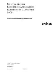
The following illustration shows the indicators on the rear of the Memory Expansion<br />
Module.<br />
Power-on<br />
LED<br />
Locate<br />
LED<br />
System<br />
error<br />
LED<br />
EXA<br />
port 1<br />
EXA<br />
port 2<br />
EXA<br />
port 3<br />
QPI<br />
port 1<br />
EXA port 1<br />
link LED<br />
EXA port 2<br />
link LED<br />
EXA port 3<br />
link LED<br />
QPI<br />
port 2<br />
QPI<br />
port 3<br />
QPI<br />
port 4<br />
Power<br />
connectors<br />
AC LED (green)<br />
DC LED (green)<br />
Power supply<br />
fault (error) LED<br />
• Power-on LED: When this green LED is lit, it indicates that the Memory Expansion<br />
Module is powered on. This LED is functionally equivalent to the power-on LED on the<br />
front of the Memory Expansion Module.<br />
• Locate LED: When this blue LED is lit, it indicates that the comm<strong>and</strong> from the server<br />
IMM to the Memory Expansion Module is complete. Use this blue LED to locate the<br />
Memory Expansion Module. The front locate LED also has a button that you can press<br />
to light up other servers or other memory expansion modules to which the Memory<br />
Expansion Module is connected. This LED is functionally equivalent to the Locate LED<br />
on the front of the Memory Expansion Module.<br />
• Power connector: Connect the power cord to this connector.<br />
• AC power LED: Each hot-swap power supply has an AC power LED <strong>and</strong> a DC<br />
power LED. When the AC power LED is lit, it indicates that sufficient power is being<br />
supplied to the power supply through the power cord. During normal operation, both<br />
the AC <strong>and</strong> DC power LEDs are lit.<br />
• DC power LED: Each hot-swap power supply has a DC power LED <strong>and</strong> an AC<br />
2–26 3850 7273–001