Development of an Augmented Reality system using ARToolKit
Development of an Augmented Reality system using ARToolKit
Development of an Augmented Reality system using ARToolKit

You also want an ePaper? Increase the reach of your titles
YUMPU automatically turns print PDFs into web optimized ePapers that Google loves.
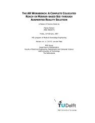
<strong>Development</strong> <strong>of</strong> <strong>an</strong> <strong>Augmented</strong> <strong>Reality</strong> <strong>system</strong> <strong>using</strong> <strong>ARToolKit</strong> <strong>an</strong>d user invisible markers<br />
2.5 Calibration<br />
Tracking is used for providing the input needed for the correct registration <strong>of</strong> virtual<br />
objects with respect to the real world. But before these two connected processes c<strong>an</strong> be<br />
carried out, <strong>an</strong>other issue which is related to both needs to be h<strong>an</strong>dled. That is,<br />
parameters <strong>of</strong> used display components in the AR <strong>system</strong> need to be determined. The<br />
complete set <strong>of</strong> procedures for estimating these parameters is called calibration.<br />
This is done for establishing the viewing projection <strong>of</strong> the used camera. From that<br />
information, correct tr<strong>an</strong>sformations for projecting virtual objects on the real world are<br />
established. These tr<strong>an</strong>sformations are me<strong>an</strong>t to mimic the intrinsic <strong>an</strong>d extrinsic<br />
parameters <strong>of</strong> the virtual camera. It is necessary to have the parameters <strong>of</strong> the real<br />
camera <strong>an</strong>d the virtual camera to coincide for projecting both real <strong>an</strong>d virtual objects in<br />
a similar way.<br />
In most cases direct interaction <strong>of</strong> the user is required for performing calibration. This<br />
precision <strong>of</strong> calibration is clearly user-dependent. Also calibration is a time-consuming<br />
task <strong>an</strong>d needs to be repeated in adv<strong>an</strong>ce each user session. To avoid this there have<br />
been developments aiming at calibration-free AR. This does not require the user to do<br />
m<strong>an</strong>ual calibration. Instead <strong>an</strong> affine mapping is constructed based upon the positions <strong>of</strong><br />
tracked fiducials. Autocalibration is <strong>an</strong>other method for reducing calibration<br />
requirements. Then redund<strong>an</strong>t sensor information is used for automatically measuring<br />
<strong>an</strong>d compensating for ch<strong>an</strong>ging calibration parameters.<br />
2.5.1 M<strong>an</strong>ual calibration<br />
M<strong>an</strong>ual calibration has been the first approach for tackling the calibration problem.<br />
Because <strong>of</strong> its maturity a r<strong>an</strong>ge <strong>of</strong> calibration algorithms have been developed. Some <strong>of</strong><br />
those use special equipment, but also more convenient methods exist. What they have in<br />
common is the division in three steps. First are obtained the 3D coordinates <strong>of</strong><br />
calibration points in the world coordinate <strong>system</strong>. The corresponding 2D points in the<br />
image pl<strong>an</strong>e are determined. From these data the tr<strong>an</strong>sformation matrix is constructed.<br />
This basic model does not take into account other factors, such as radial distortion<br />
caused by optical elements. However, methods that also compensate for that also exist.<br />
There are differences between calibration methods for video see-through <strong>an</strong>d optical<br />
see-through HMDs. Calibration <strong>of</strong> a video see-through HMD c<strong>an</strong> be done by <strong>using</strong><br />
image processing techniques to determine tr<strong>an</strong>sformation matrices from relations<br />
between real points <strong>an</strong>d their projected counterparts. That procedure will not be<br />
discussed here, but is explained in the following chapter on ARTooKit.<br />
For optical see-through HMDs this c<strong>an</strong> not be used since a video stream is not available.<br />
Users will have to match real points in space against its virtually projected point. In<br />
[Azu94] is described <strong>an</strong> algorithm for m<strong>an</strong>ual calibration <strong>of</strong> optical see-through HMDs.<br />
The real wooden frame used for the calibration is shown in Figure 2.31. The virtual<br />
objects to be calibrated against this real object are three mutually orthogonal lines,<br />
forming a coordinate <strong>system</strong>. Figure 2.32 shows the alignment <strong>of</strong> the virtual axis with<br />
the real box. Four parameters are measured; location <strong>of</strong> the frame, apparent centre <strong>of</strong><br />
the virtual image, tr<strong>an</strong>sformation between tracker space <strong>an</strong>d eye space, <strong>an</strong>d FOV. This is<br />
22