John Deere AutoTrac™ Controller - StellarSupport - John Deere
John Deere AutoTrac™ Controller - StellarSupport - John Deere
John Deere AutoTrac™ Controller - StellarSupport - John Deere

You also want an ePaper? Increase the reach of your titles
YUMPU automatically turns print PDFs into web optimized ePapers that Google loves.
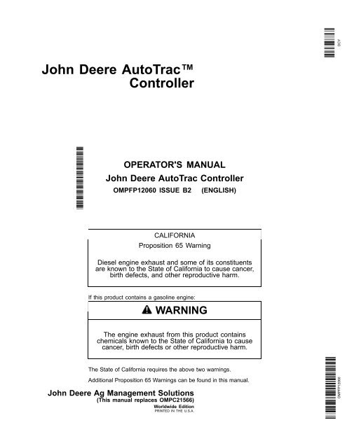
<strong>John</strong> <strong>Deere</strong> AutoTrac<br />
<strong>Controller</strong><br />
*OMPFP12060*<br />
OPERATOR'S MANUAL<br />
<strong>John</strong> <strong>Deere</strong> AutoTrac <strong>Controller</strong><br />
OMPFP12060 ISSUE B2 (ENGLISH)<br />
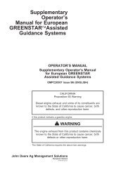
CALIFORNIA<br />
Proposition 65 Warning<br />
Diesel engine exhaust and some of its constituents<br />
are known to the State of California to cause cancer,<br />
birth defects, and other reproductive harm.<br />
If this product contains a gasoline engine:<br />
WARNING<br />
The engine exhaust from this product contains<br />
chemicals known to the State of California to cause<br />
cancer, birth defects or other reproductive harm.<br />
The State of California requires the above two warnings.<br />
Additional Proposition 65 Warnings can be found in this manual.<br />
<strong>John</strong> <strong>Deere</strong> Ag Management Solutions<br />
(This manual replaces OMPC21566)<br />
Worldwide Edition<br />
PRINTED IN THE U.S.A.<br />
DCY<br />
OMPFP12060
www.<strong>StellarSupport</strong>.com<br />
Introduction<br />
NOTE: Product functionality may not be fully represented in this document due to product changes occurring after the time of printing. Read the<br />
latest Operator's Manual and Quick Reference Guide prior to operation. To obtain a copy, see your dealer or visit www.<strong>StellarSupport</strong>.com<br />
Foreword<br />
This <strong>John</strong> <strong>Deere</strong> AutoTrac <strong>Controller</strong> Operator's Manual<br />
is to be used with the Guidance Operator's Manual.<br />
READ BOTH MANUALS carefully to learn how to operate<br />
and service your system correctly. Failure to do so could<br />
OUO6050,0000FB1 -19-10AUG10-1/1<br />
result in personal injury or equipment damage. These<br />
manuals may also be available in other languages. (See<br />
your <strong>John</strong> <strong>Deere</strong> dealer to order.)<br />
BA31779,00003AC -19-09FEB12-1/1<br />
031312<br />
PN=2
Contents<br />
Page<br />
Safety<br />
Recognize Safety Information ............................05-1<br />
Understand Signal Words...................................05-1<br />
Follow Safety Instructions...................................05-1<br />
Practice Safe Maintenance.................................05-2<br />
Handle Electronic Components and<br />
Brackets Safely ..............................................05-2<br />
Operate Guidance Systems Safely ....................05-3<br />
Use Seat Belt Properly .......................................05-3<br />
Use AutoTrac <strong>Controller</strong> on Approved Vehicles ..05-3<br />
Inspect AccuGuide PressureTransducer<br />
Valve for Leaks.....................................05-4<br />
Safety Signs<br />
Automatic Guidance System Detected...............10-1<br />
<strong>John</strong> <strong>Deere</strong> AutoTrac <strong>Controller</strong><br />
AutoTrac Accuracy .............................................15-1<br />
General Information............................................15-1<br />
AutoTrac <strong>Controller</strong> Compatibility.......................15-2<br />
Master Switch.....................................................15-2<br />
AutoTrac Settings ...............................................15-3<br />
Activity Monitor ...................................................15-4<br />
AutoTrac <strong>Controller</strong> Calibration ..........................15-5<br />
Wheel Angle Sensor Calibration.........................15-6<br />
Valve Calibration.................................................15-9<br />
Failed Calibrations............................................ 15-11<br />
Necessary Conditions for Activating AutoTrac ..15-12<br />
<strong>John</strong> <strong>Deere</strong> AutoTrac <strong>Controller</strong> Troubleshooting<br />
AutoTrac <strong>Controller</strong> ............................................20-1<br />
Diagnostic Readings...........................................20-2<br />
AutoTrac <strong>Controller</strong> Diagnostic Trouble Codes ..20-3<br />
Stop Codes.........................................................20-5<br />
GS3 Display 2630<br />
Automatic Guidance System Detected...............25-1<br />
Enabling System.................................................25-1<br />
Activating System...............................................25-1<br />
Deactivating System...........................................25-2<br />
StarFire ..............................................................25-2<br />
AutoTrac Setup...................................................25-3<br />
GS2 Display 2600<br />
AutoTrac Detected..............................................30-1<br />
Enabling System.................................................30-1<br />
Activating System...............................................30-1<br />
Deactivating System...........................................30-2<br />
Page<br />
StarFire ..............................................................30-2<br />
Setup ..................................................................30-3<br />
Tuning Tips, Tricks, and Precautions................30-10<br />
Troubleshooting................................................ 30-11<br />
Troubleshooting—GS2 2600 and GS3 2630<br />
Displays<br />
Guidance Alarms................................................35-1<br />
Diagnostic Addresses.........................................35-2<br />
Trouble Codes ....................................................35-3<br />
Trouble Code Pop-Up Boxes—Guidance<br />
Software ................................................35-4<br />
GS2 Display 1800<br />
Start-Up Screen..................................................40-1<br />
Enabling System.................................................40-1<br />
Activating System...............................................40-1<br />
GreenStar Run Page..........................................40-2<br />
Enabling AutoTrac ..............................................40-6<br />
AutoTrac Status Pie............................................40-7<br />
Reactivating AutoTrac on Next Pass..................40-8<br />
Deactivating AutoTrac ........................................40-8<br />
StarFire ..............................................................40-9<br />
Guidance Settings ............................................40-10<br />
AutoTrac Settings ............................................. 40-11<br />
Advanced AutoTrac Settings ............................40-12<br />
Troubleshooting—GS2 Display 1800<br />
Trouble Codes ....................................................45-1<br />
Diagnostic Addresses.........................................45-1<br />
Guidance Alarms................................................45-3<br />
AutoTrac Deactivation Message.........................45-4<br />
Diagnostic Addresses.........................................45-5<br />
Specifications<br />
EC Declaration of Conformity.............................50-1<br />
Original Instructions. All information, illustrations and specifications in this<br />
manual are based on the latest information available at the time of publication.<br />
The right is reserved to make changes at any time without notice.<br />
i<br />
COPYRIGHT © 2012<br />
DEERE & COMPANY<br />
Moline, Illinois<br />
All rights reserved.<br />
A <strong>John</strong> <strong>Deere</strong> ILLUSTRUCTION ® Manual<br />
031312<br />
PN=1
Contents<br />
ii<br />
031312<br />
PN=2
Recognize Safety Information<br />
This is a safety-alert symbol. When you see this symbol<br />
on your machine or in this manual, be alert to the potential<br />
for personal injury.<br />
Follow recommended precautions and safe operating<br />
practices.<br />
Understand Signal Words<br />
A signal word—DANGER, WARNING, or CAUTION—is<br />
used with the safety-alert symbol. DANGER identifies the<br />
most serious hazards.<br />
DANGER or WARNING safety signs are located near<br />
specific hazards. General precautions are listed on<br />
CAUTION safety signs. CAUTION also calls attention to<br />
safety messages in this manual.<br />
Follow Safety Instructions<br />
Carefully read all safety messages in this manual and on<br />
your machine safety signs. Keep safety signs in good<br />
condition. Replace missing or damaged safety signs. Be<br />
sure new equipment components and repair parts include<br />
the current safety signs. Replacement safety signs are<br />
available from your <strong>John</strong> <strong>Deere</strong> dealer.<br />
There can be additional safety information contained on<br />
parts and components sourced from suppliers that is not<br />
reproduced in this operator's manual.<br />
Learn how to operate the machine and how to use controls<br />
properly. Do not let anyone operate without instruction.<br />
Keep your machine in proper working condition.<br />
Unauthorized modifications to the machine may impair the<br />
function and/or safety and affect machine life.<br />
Safety<br />
05-1<br />
T81389 —UN—07DEC88<br />
DX,ALERT -19-29SEP98-1/1<br />
TS187 —19—30SEP88<br />
DX,SIGNAL -19-03MAR93-1/1<br />
If you do not understand any part of this manual and need<br />
assistance, contact your <strong>John</strong> <strong>Deere</strong> dealer.<br />
TS201 —UN—23AUG88<br />
DX,READ -19-16JUN09-1/1<br />
031312<br />
PN=5
Practice Safe Maintenance<br />
Understand service procedure before doing work. Keep<br />
area clean and dry.<br />
Never lubricate, service, or adjust machine while it is<br />
moving. Keep hands, feet , and clothing from power-driven<br />
parts. Disengage all power and operate controls to relieve<br />
pressure. Lower equipment to the ground. Stop the<br />
engine. Remove the key. Allow machine to cool.<br />
Securely support any machine elements that must be<br />
raised for service work.<br />
Keep all parts in good condition and properly installed.<br />
Fix damage immediately. Replace worn or broken parts.<br />
Remove any buildup of grease, oil, or debris.<br />
On self-propelled equipment, disconnect battery ground<br />
cable (-) before making adjustments on electrical systems<br />
or welding on machine.<br />
On towed implements, disconnect wiring harnesses from<br />
tractor before servicing electrical system components or<br />
welding on machine.<br />
Handle Electronic Components and Brackets<br />
Safely<br />
Falling while installing or removing electronic components<br />
mounted on equipment can cause serious injury. Use a<br />
ladder or platform to easily reach each mounting location.<br />
Use sturdy and secure footholds and handholds. Do not<br />
install or remove components in wet or icy conditions.<br />
If installing or servicing a RTK base station on a tower or<br />
other tall structure, use a certified climber.<br />
If installing or servicing a global positioning receiver mast<br />
used on an implement, use proper lifting techniques and<br />
wear proper protective equipment. The mast is heavy and<br />
can be awkward to handle. Two people are required when<br />
mounting locations are not accessible from the ground<br />
or from a service platform.<br />
Safety<br />
05-2<br />
TS218 —UN—23AUG88<br />
DX,SERV -19-17FEB99-1/1<br />
TS249 —UN—23AUG88<br />
DX,WW,RECEIVER -19-24AUG10-1/1<br />
031312<br />
PN=6
Operate Guidance Systems Safely<br />
Do not use guidance systems on roadways. Always turn<br />
off (disable) guidance systems before entering a roadway.<br />
Do not attempt to turn on (activate) a guidance system<br />
while transporting on a roadway.<br />
Guidance systems are intended to aid the operator in<br />
performing field operations more efficiently. The operator<br />
is always responsible for the machine path. Guidance<br />
systems do not automatically detect or prevent collisions<br />
with obstacles or other machines.<br />
Guidance Systems include any application that automates<br />
vehicle steering. This includes, but may not be limited<br />
to, AutoTrac, iGuide, iTEC Pro, ATU, RowSense, and<br />
Machine Sync.<br />
To prevent injury to the operator and bystanders:<br />
• Never get on or off a moving vehicle.<br />
Use Seat Belt Properly<br />
Use a seat belt when you operate with a roll-over<br />
protective structure (ROPS) or cab to minimize chance of<br />
injury from an accident such as an overturn.<br />
Do not use a seat belt if operating without a ROPS or cab.<br />
Replace entire seat belt if mounting hardware, buckle,<br />
belt, or retractor show signs of damage.<br />
Inspect seat belt and mounting hardware at least<br />
once a year. Look for signs of loose hardware or belt<br />
damage, such as cuts, fraying, extreme or unusual wear,<br />
discoloration, or abrasion. Replace only with replacement<br />
parts approved for your machine. See your <strong>John</strong> <strong>Deere</strong><br />
dealer.<br />
Safety<br />
Use AutoTrac <strong>Controller</strong> on Approved Vehicles<br />
Use AutoTrac <strong>Controller</strong> only on Approved Vehicles—see<br />
<strong>StellarSupport</strong>.<strong>Deere</strong>.com for list of approved vehicles.<br />
When activity monitor is selected, AutoTrac <strong>Controller</strong><br />
looks for operator activity every seven minutes. Operator<br />
05-3<br />
• Verify the machine, implement, and guidance system<br />
are set up correctly.<br />
- If using iTEC Pro, verify accurate boundaries have<br />
been defined.<br />
- If using Machine Sync, verify the follower’s home<br />
point is calibrated with sufficient space between the<br />
vehicles.<br />
• Remain alert and pay attention to the surrounding<br />
environment.<br />
• Take control of the steering wheel, when necessary, to<br />
avoid field hazards, bystanders, equipment, or other<br />
obstacles.<br />
• Stop operation if poor visibility conditions impair your<br />
ability to operate the machine or identify people or<br />
obstacles in the machine path.<br />
• Consider field conditions, visibility, and vehicle<br />
configuration when selecting vehicle speed.<br />
JS56696,0000ABC -19-13DEC11-1/1<br />
TS205 —UN—23AUG88<br />
DX,ROPS1 -19-29OCT07-1/1<br />
will receive a time-out warning 15 seconds before<br />
AutoTrac deactivates. Pressing Resume will reset activity<br />
monitor timer.<br />
JS56696,0000615 -19-14SEP11-1/1<br />
031312<br />
PN=7
Inspect AccuGuide Pressure<br />
Transducer Valve for Leaks<br />
Regularly inspect the AccuGuide Pressure Transducer<br />
Valve for leaks. Hydraulic oil leaking from this valve may<br />
result in steering wheel motion not deactivating AutoTrac.<br />
Consult your dealer if leaks are found.<br />
Safety<br />
05-4<br />
AccuGuide Pressure Transducer Valve<br />
PC13830 —UN—14JUN11<br />
JS56696,0000535 -19-14JUN11-1/1<br />
031312<br />
PN=8
Automatic Guidance System Detected<br />
Each time a machine equipped with AutoTrac is started,<br />
this screen will appear as a reminder of operator<br />
responsibilities when using AutoTrac steering system.<br />
Safety Signs<br />
10-1<br />
Automatic Guidance<br />
PC13157 —19—17FEB11<br />
CF86321,0000399 -19-01JUN11-1/1<br />
031312<br />
PN=9
AutoTrac Accuracy<br />
<strong>John</strong> <strong>Deere</strong> AutoTrac <strong>Controller</strong><br />
IMPORTANT: The AutoTrac system relies on the GPS<br />
system operated by the government of the<br />
United States, which is solely responsible for<br />
its accuracy and maintenance. The system is<br />
subject to changes that could affect accuracy<br />
and performance of all GPS equipment.<br />
The overall AutoTrac system accuracy is dependent upon<br />
many variables. The equation looks like:<br />
AutoTrac System Accuracy = Signal accuracy + Vehicle<br />
Setup + Implement Setup + Field/Soil Conditions.<br />
It is very important to remember:<br />
• Receiver has to go through a warm-up period after<br />
starting.<br />
• Vehicle is setup properly (ballasted according to vehicle<br />
operator manual, etc.)<br />
General Information<br />
All operators must be familiar with AutoTrac system and<br />
operating characteristics prior to operation. The following<br />
is a suggested procedure for operator to become familiar<br />
with system:<br />
1. Read and understand Operators Manual for GreenStar<br />
Guidance—Parallel Tracking and AutoTrac Assisted<br />
Steering Systems.<br />
2. Choose an open area free of hazards (ditches,<br />
buildings, etc.).<br />
3. Set Track Spacing to 92.0 meters (300 ft).<br />
4. Set a Track 0 (A—B Line).<br />
NOTE: Operate vehicle at a speed you are comfortable,<br />
recommend less than 8 km/h (5 mph).<br />
5. Enable AutoTrac on display by turning Steer ON.<br />
6. Press Resume switch to activate AutoTrac. (See<br />
Activating system later in this section).<br />
7. After driving a short distance, then turn steering wheel<br />
to turn vehicle off track to deactivate AutoTrac. (See<br />
Deactivating System later in this section).<br />
8. Practice Activating AutoTrac at different distances<br />
before and after crossing track and at different angles.<br />
Increase and decrease speeds to simulate different<br />
operating conditions.<br />
9. Reduce Track Spacing to acquire multiple tracks and<br />
continue practicing activating AutoTrac at different<br />
angles and varying speeds to understand how<br />
AutoTrac behaves under different conditions.<br />
15-1<br />
• Implement is setup to run properly (wear parts such<br />
as shanks, shovels, and sweeps are in good working<br />
condition and correctly spaced).<br />
• Understand how field/soil conditions affect system<br />
(loose soil requires more steering than firm soil, but firm<br />
soil can cause uneven draft loads).<br />
See the AUTOTRAC SYSTEM ACCURACY section<br />
in DIAGNOSTICS section of this manual for more<br />
information.<br />
IMPORTANT: Although AutoTrac system can be<br />
activated when SF2 (or SF1 if using AutoTrac<br />
SF1 activation) correction signal is confirmed,<br />
system accuracy may continue to increase<br />
after powering up system.<br />
AutoTrac SF2 activation will operate on a SF1, SF2, or<br />
RTK signal.<br />
AutoTrac SF1 activation will operate on a SF1 signal only.<br />
JS56696,0000614 -19-15JUN09-1/1<br />
Always be prepared to resume manual control if AutoTrac<br />
does not perform expected maneuvers or machine course<br />
must be changed to avoid injury or property damage.<br />
Operator can regain manual steering by turning steering<br />
wheel or Disabling AutoTrac by turning Steer off on<br />
display. It is recommended practice to be as close as<br />
possible to desired track prior to activating AutoTrac. This<br />
will ensure correct track and direction are acquired.<br />
The AutoTrac basic system is intended to be used as<br />
an assistance tool to mechanical markers on planters.<br />
Operator must evaluate overall system accuracy to<br />
determine specific field operations where assisted<br />
steering may be used. This evaluation is necessary<br />
because accuracy required for various field operations<br />
may differ depending on farming operation. Because<br />
AutoTrac uses StarFire differential correction network<br />
along with Global Positioning System (GPS), slight shifts<br />
in position may occur over time.<br />
To operate AutoTrac operator must set track 0 (similar to<br />
parallel tracking) and all tracks are drawn parallel to track<br />
0 using track spacing.<br />
The AutoTrac system operating status can exist at four<br />
levels: INSTALLED, CONFIGURED, ENABLED, and<br />
ACTIVATED.<br />
After enabling AutoTrac (see Enabling AutoTrac),<br />
AutoTrac is activated by pressing resume switch<br />
on armrest (see Activating AutoTrac). To return to<br />
manual steering, operator must deactivate system (see<br />
Deactivating System).<br />
If required track can be shifted left, right or centered using<br />
shift track feature on display. (See Shift Track).<br />
BA31779,00003C1 -19-29FEB12-1/1<br />
031312<br />
PN=10
AutoTrac <strong>Controller</strong> Compatibility<br />
For a complete list of compatible machines please visit<br />
www.<strong>StellarSupport</strong>.com.<br />
AFS AccuGuide, Case, Magnum, MX, New Holland, and IntelliSteer<br />
are U.S.-registered trademarks of CNH Global<br />
Master Switch<br />
If present, machine manufacturer supplied Master Switch<br />
must be set to the ON position (B) to activate AutoTrac<br />
components.<br />
A—OFF Position B—ON Position<br />
<strong>John</strong> <strong>Deere</strong> AutoTrac <strong>Controller</strong><br />
15-2<br />
AutoTrac <strong>Controller</strong> Compatibility<br />
Case MX Magnum 215<br />
AccuGuide Ready (MY2006 to<br />
245<br />
MY2010)<br />
275<br />
305<br />
Case MX Magnum 335<br />
AccuGuide Ready (MY2008 to<br />
MY2010)<br />
New Holland® TG IntelliSteer 215<br />
Ready (MY2006 to MY2010)<br />
245<br />
275<br />
305<br />
New Holland® IntelliSteer T8010<br />
Ready (MY2008 to MY2010)<br />
T8020<br />
T8030<br />
T8040<br />
T8050<br />
Master Switch<br />
BA31779,00003AF -19-15FEB12-1/1<br />
PC11968 —UN—09APR09<br />
BA31779,00003B2 -19-09FEB12-1/1<br />
031312<br />
PN=11
AutoTrac Settings<br />
A—View Tab<br />
B—Guidance Settings Tab<br />
<strong>John</strong> <strong>Deere</strong> AutoTrac <strong>Controller</strong><br />
C—ShiftTrack Settings<br />
D—Tracking Mode Drop-Down<br />
Menu<br />
15-3<br />
E—Implement Guidance Mode<br />
Drop-Down Menu<br />
F— General Settings<br />
G—Lightbar Settings<br />
H—AutoTrac Advanced Settings<br />
PC14326 —UN—07DEC11<br />
BA31779,00003BB -19-16FEB12-1/1<br />
031312<br />
PN=12
Activity Monitor<br />
Operator Detection Timeout<br />
The system has not detected any recent operator activity.<br />
AutoTrac will deactivate in: 11 seconds.<br />
Press the Resume Switch or acknowledge this alarm to<br />
prevent deactivation.<br />
The Activity Monitor will monitor the status of the operator<br />
by requiring the operator to provide input to the display<br />
every 7 minutes.<br />
To reset the Activity Monitor, push the resume switch or<br />
click the Enter button on the pop-up screen.<br />
<strong>John</strong> <strong>Deere</strong> AutoTrac <strong>Controller</strong><br />
15-4<br />
Operator Detection Timeout<br />
PC12143 —UN—30JUN09<br />
JS56696,0000538 -19-30JUN09-1/1<br />
031312<br />
PN=13
AutoTrac <strong>Controller</strong> Calibration<br />
Select GUIDANCE softkey >> GUIDANCE SETTINGS<br />
tab >> CHANGE AUTOTRAC CONTROLLER SETTINGS<br />
button >>CAL button<br />
NOTE: Calibration procedure must be complete with a<br />
passing status prior to using AutoTrac.<br />
Read all instructions before calibrating the AutoTrac<br />
<strong>Controller</strong><br />
• The Calibration procedure consists of 12 Calibration<br />
Steps.<br />
• Drive tractor slowly at full throttle for approximately<br />
2 to 5 minutes to bring hydraulic fluid to operating<br />
temperature before beginning calibration procedure.<br />
• Calibration procedure will require a large, open, level<br />
surface to complete the required steps.<br />
• Calibration procedure must be completed prior to using<br />
AutoTrac for the first time.<br />
• Each calibration step allows three failures before that<br />
step is exited and entire calibration must be repeated.<br />
• If the calibration procedure fails, the system will use the<br />
last valid calibration until another valid calibration has<br />
been completed.<br />
NOTE: Machine manufacturer supplied Master Switch<br />
must be set to the ON position when performing<br />
AutoTrac <strong>Controller</strong> Calibration procedure.<br />
NOTE: At any time during calibration, the operator<br />
may take control of the system by grabbing the<br />
steering wheel or stopping the machine.<br />
Before beginning calibration, drive the machine until the<br />
hydraulic oil is at operating temperature. This will improve<br />
calibration accuracy.<br />
<strong>John</strong> <strong>Deere</strong> AutoTrac <strong>Controller</strong><br />
15-5<br />
PC8673 —UN—14OCT07<br />
PC11948 —UN—30JUN09<br />
PC12145 —UN—30JUN09<br />
GUIDANCE softkey<br />
GUIDANCE SETTINGS tab<br />
CHANGE AUTOTRAC CONTROLLER SETTINGS button<br />
PC12144 —UN—30JUN09<br />
CAL button<br />
Calibration procedure will require a large, open, level<br />
surface to complete the required steps.<br />
Park the machine on flat level surface, then select the<br />
Next button to begin.<br />
BA31779,00003B3 -19-09FEB12-1/1<br />
031312<br />
PN=14
Wheel Angle Sensor Calibration<br />
Select Wheel Angle Sensor Calibration button to begin<br />
calibrating the Wheel Angle Sensor.<br />
The system will Auto Detect the Wheel Angle Sensor.<br />
NOTE: Wheel Angle Sensor Calibration must be complete<br />
before Valve Calibration can be performed.<br />
Follow the on screen instructions for the next five steps.<br />
Complete each instruction and then select the next button<br />
to contine.<br />
NOTE: The following steps may require using the<br />
lowest forward gear to move ahead slowly<br />
allowing full range of steering.<br />
The system will display a progress meter at the top of each<br />
page showing the operator calibration step completion.<br />
Once the Wheel Angle Sensor Calibration has been<br />
completed, the system will return to the Calibration Screen<br />
displaying PASS next to Wheel Angle Sensor.<br />
If the system FAILS, calibration, it will display FAIL next to<br />
the Calibration that has failed.<br />
Once sensor is detected, select Next to continue.<br />
If system fails to detect sensor, check connections to<br />
Wheel Angle Sensor.<br />
<strong>John</strong> <strong>Deere</strong> AutoTrac <strong>Controller</strong><br />
15-6<br />
A—Wheel Angle Sensor<br />
Calibration<br />
B—Valve Calibration<br />
JS56696,000062B -19-01JUL09-1/7<br />
Continued on next page JS56696,000062B -19-01JUL09-2/7<br />
PC12031 —UN—05MAY09<br />
PC12156 —UN—14JUL09<br />
031312<br />
PN=15
Turn wheel until LEFT stop, then select Next button.<br />
NOTE: You may need to drive forward slowly to allow the<br />
wheels to reach their full range of motion.<br />
Turn wheels until RIGHT stop, then select the Next button.<br />
NOTE: You may need to drive forward slowly to allow the<br />
wheels to reach their full range of motion.<br />
<strong>John</strong> <strong>Deere</strong> AutoTrac <strong>Controller</strong><br />
15-7<br />
JS56696,000062B -19-01JUL09-3/7<br />
Continued on next page JS56696,000062B -19-01JUL09-4/7<br />
PC12157 —UN—14JUL09<br />
PC12164 —UN—16JUL09<br />
031312<br />
PN=16
Turn wheel back to CENTER with wheels straight, then<br />
select the Next button.<br />
NOTE: You may need to drive forward slowly to allow the<br />
wheels to reach their full range of motion.<br />
Drive in a straight line at or above 16 km/h (10 mph) until<br />
calibration is complete.<br />
IMPORTANT: Calibration procedure will require a<br />
large, open, level surface to complete the<br />
required steps. Ensure the area is clear of<br />
any obstacles and traffic.<br />
NOTE: Keep steering corrections to a minimum. Steering<br />
wheel movement may result in an extended<br />
calibration period or calibration failure.<br />
<strong>John</strong> <strong>Deere</strong> AutoTrac <strong>Controller</strong><br />
15-8<br />
JS56696,000062B -19-01JUL09-5/7<br />
Continued on next page JS56696,000062B -19-01JUL09-6/7<br />
PC12165 —UN—16JUL09<br />
PC12146 —UN—01JUL09<br />
031312<br />
PN=17
Once System has passed the wheel angle sensor<br />
calibration, select the next button.<br />
Next, select the Valve Calibration button to begin<br />
calibrating the Steering Valve.<br />
The system will display some initial instructions. Please<br />
read and follow these instructions. Once the instructions<br />
have been read, select the Next button.<br />
Calibration will need to be repeated until PASS is<br />
displayed next to Valve Calibration.<br />
A—Wheel Angle Sensor<br />
Calibration<br />
Valve Calibration<br />
B—Valve Calibration<br />
Before beginning calibration, drive the machine until the<br />
hydraulic oil is at operating temperature. This will improve<br />
calibration accuracy.<br />
1. Begin moving forward in the lowest gear at the<br />
maximum RPM.<br />
2. Select the Next button to begin.<br />
3. Wait for calibration to finish.<br />
Repeat steps 2 and 3 until three left turn and three right<br />
turn calibrations have been completed.<br />
Attention: During calibration, machine will move slowly<br />
to left or right. It may move unpredictably.<br />
IMPORTANT: Calibration procedure will require a<br />
large, open, level surface to complete the<br />
required steps. Ensure the area is clear of<br />
any obstacles and traffic.<br />
<strong>John</strong> <strong>Deere</strong> AutoTrac <strong>Controller</strong><br />
15-9<br />
JS56696,000062B -19-01JUL09-7/7<br />
Continued on next page JS56696,000062D -19-01JUL09-1/4<br />
PC11941 —UN—08APR09<br />
PC12160 —UN—14JUL09<br />
031312<br />
PN=18
Turn steering wheel back to center with wheels straight,<br />
then select the Next button.<br />
Calibrating Left<br />
NOTE: Moving the steering wheel until instructed<br />
cancels the current calibration.<br />
<strong>John</strong> <strong>Deere</strong> AutoTrac <strong>Controller</strong><br />
PC12147 —UN—01JUL09<br />
15-10<br />
Calibrating Right<br />
JS56696,000062D -19-01JUL09-2/4<br />
NOTE: After every left and right calibration, turn<br />
steering wheel back to center with wheels<br />
straight, then select Next.<br />
Continued on next page JS56696,000062D -19-01JUL09-3/4<br />
PC12161 —UN—14JUL09<br />
PC12148 —UN—01JUL09<br />
031312<br />
PN=19
Once all steps have been completed, the system will<br />
return to the calibration screen and display PASS next<br />
to Valve Calibration.<br />
Once the system has displayed PASS for both calibrations,<br />
select the Next button and begin using AutoTrac.<br />
A—Wheel Angle Sensor<br />
Calibration<br />
Failed Calibrations<br />
B—Valve Calibration<br />
NOTE: Calibration failed using previous calibration values.<br />
If calibration failure persists, check the Message Center<br />
and/or contact your <strong>John</strong> <strong>Deere</strong> dealer.<br />
If the system fails calibration, FAIL will be displayed next<br />
to the calibration that has failed.<br />
Calibration will need to be repeated until PASS is<br />
displayed.<br />
A Failed calibration may be the result of:<br />
• Incorrect inputs provided by the operator<br />
• Not enough area to complete calibration without<br />
stopping during the calibration step<br />
• Grabbing the steering wheel to avoid obstacles<br />
• Wheel angle sensor not responding<br />
• Valve not responding.<br />
• Machine hardware failure<br />
NOTE: Newer tractors may require multiple attempts<br />
to pass the valve calibration procedure.<br />
A—Wheel Angle Sensor<br />
Calibration<br />
B—Valve Calibration<br />
<strong>John</strong> <strong>Deere</strong> AutoTrac <strong>Controller</strong><br />
15-11<br />
PC11947 —UN—09APR09<br />
JS56696,000062D -19-01JUL09-4/4<br />
PC12162 —UN—14JUL09<br />
JS56696,0000534 -19-30JUN09-1/1<br />
031312<br />
PN=20
Necessary Conditions for Activating<br />
AutoTrac<br />
Track No. 0<br />
Track<br />
Spacing<br />
Track No. 1-S<br />
40%<br />
40%<br />
<strong>John</strong> <strong>Deere</strong> AutoTrac <strong>Controller</strong><br />
Off-Track<br />
Lateral Error<br />
Track No. changes at 50%<br />
Once tractor is at end of row operator must turn system<br />
to next pass. By turning steering wheel, AutoTrac is<br />
deactivated. Operator must turn onto next track.<br />
AutoTrac can be activated by pressing resume switch only<br />
after following conditions are met:<br />
NOTE: Calibration procedure must be complete with a<br />
passing status prior to using AutoTrac.<br />
Once two pieces of the PIE are achieved, the operator<br />
can enable AutoTrac by selecting the Steer On icon.<br />
If two pieces of the PIE can not be achieved, the operator<br />
will not be able to activate AutoTrac.<br />
• A diagnostic button is located next to the PIE icon.<br />
• If two pieces of the PIE can not be achieved, select<br />
wrench icon to view AutoTrac Diagnostics.<br />
The Diagnostics page will indicate what is needed for each<br />
of the four PIE pieces and the status of all requirements.<br />
AutoTrac may not become available until hydraulic<br />
temperature has reached pre set level (1 PIE piece only<br />
until warm). This issue will not provide any diagnostic<br />
code or show in the status menu.<br />
15-12<br />
80˚<br />
80˚<br />
Track Heading<br />
Error<br />
1. System is enabled (steering ON on RUN screen).<br />
2. The machine is within 40% of track spacing.<br />
3. Track heading is within 80° of track.<br />
PC11972 —UN—09APR09<br />
PC11971 —UN—09APR09<br />
PC11973 —UN—09APR09<br />
Steer On icon<br />
Pie Pieces<br />
AutoTrac Diagnostics Wrench<br />
PC7051 —19—04FEB02<br />
OUO6050,0000D61 -19-22APR09-1/2<br />
OUO6050,0000D61 -19-22APR09-2/2<br />
031312<br />
PN=21
<strong>John</strong> <strong>Deere</strong> AutoTrac <strong>Controller</strong> Troubleshooting<br />
AutoTrac <strong>Controller</strong><br />
Symptom Problem Solution<br />
AutoTrac <strong>Controller</strong> won’t activate.<br />
AutoTrac will not resume.<br />
AutoTrac <strong>Controller</strong> does not<br />
appear on INFO or SETUP screens<br />
Stop Code encountered See list of stop codes to find issue<br />
System not recognizing AutoTrac<br />
<strong>Controller</strong> on CAN bus line<br />
Ensure AutoTrac <strong>Controller</strong> is<br />
connected to GreenStar Harness and<br />
receiving power<br />
Check for blown fuses in ATC wiring<br />
harness<br />
Direction can not be determined Old TCM Software Update TCM Software to newest<br />
software (Version 1.08 or greater)<br />
Tractor acquires guidance line but<br />
tracks 25 to 518 cm (10 to 204 in.)<br />
to right or left of line.<br />
No differential Correction Establish differential correction<br />
No GPS Establish signal<br />
ATC did not establish direction<br />
correctly<br />
AutoTrac <strong>Controller</strong> has encountered<br />
a bad wheel angle sensor calibration<br />
and has an incorrect wheel angle<br />
sensor bias.<br />
20-1<br />
Drive forward at a speed greater than<br />
1.6 km/h (1 mph) and turn steering<br />
wheel greater than 45 degrees in one<br />
direction<br />
Recalibrate wheel angle sensor and<br />
reacquire line to ensure problem is<br />
corrected.<br />
OUO6050,0000D63 -19-15JUL09-1/1<br />
031312<br />
PN=22
Diagnostic Readings<br />
A—View Drop-Down Menu<br />
B—Software Version<br />
C—Hardware Part Number<br />
D—Serial Number<br />
E—Mode Status<br />
<strong>John</strong> <strong>Deere</strong> AutoTrac <strong>Controller</strong> Troubleshooting<br />
F— Total Hours<br />
G—AutoTrac Hours<br />
H—Resume Switch Status<br />
I— Seat Switch Status<br />
J— Stop Code<br />
Read the latest Operator Manual prior to operation.<br />
To obtain a copy, see your dealer or visit<br />
www.<strong>StellarSupport</strong>.com.<br />
20-2<br />
K—Wheel Angle Sensor Type<br />
L— WAS Calibration<br />
M—Left WAS Calibration Number<br />
N—Right WAS Calibration<br />
Number<br />
O—Center WAS Calibration<br />
Number<br />
P—WAS Calibration Complete<br />
Status<br />
Q—Valve Calibration<br />
R—Left Valve Calibration Number<br />
S—Right Valve Calibration<br />
Number<br />
T— Valve Calibration Complete<br />
Status<br />
PC12149 —UN—02JUL09<br />
OUO6050,0000D6A -19-21APR09-1/1<br />
031312<br />
PN=23
AutoTrac <strong>Controller</strong> Diagnostic Trouble<br />
Codes<br />
Trouble Codes<br />
Select TROUBLE CODES button and a list of controllers<br />
will appear and controllers with diagnostic codes are<br />
indicated.<br />
Individual controllers can be accessed by pressing<br />
ENTER button to view codes for that controller.<br />
Codes can also be displayed for all controllers by<br />
selecting SHOW ALL button and pressing ENTER button.<br />
Codes can be relayed to a <strong>John</strong> <strong>Deere</strong> dealer to assist in<br />
diagnosing machine problems.<br />
<strong>John</strong> <strong>Deere</strong> AutoTrac <strong>Controller</strong> Troubleshooting<br />
PC8663 —UN—05AUG05<br />
PC8655 —UN—05AUG05<br />
MENU button<br />
MESSAGE CENTER button (With Info Icon)<br />
PC8669 —UN—05AUG05<br />
TROUBLE CODES softkey<br />
SPN FMI Description<br />
000168 03<br />
Indicates SSU unswitched supply voltage (cc# 182) out of<br />
range high<br />
000168 04<br />
Indicates SSU unswitched supply voltage (cc# 182) out of<br />
range low<br />
000232 09 Indicates differential correction signal to GPS is not available<br />
000517 09 Indicates GPS Speed Message Missing<br />
Indicates control unit SSU being reprogrammed (boot block<br />
000628 12<br />
generated). Reprogram control unit SSU. Replace control<br />
unit SSU if condition persists.<br />
Indicates incomplete calibration of steering valve.<br />
000630 13<br />
Wheel Angle Sensor calibration incomplete.<br />
AutoTrac will remain disabled until successful calibration of<br />
system.<br />
Indicates sensor supply voltage (cc# 733) for steering wheel<br />
003509 03<br />
pressure sensor and/or wheel angle position sensor out of<br />
range high.<br />
Indicates sensor supply voltage (cc# 733) for steering wheel<br />
003509 04<br />
pressure sensor and/or wheel angle position sensor out of<br />
range high.<br />
Indicates sensor supply current too high on (cc# 733) for<br />
003509 05<br />
steering wheel pressure sensor and/or wheel angle position<br />
sensor.<br />
Indicates sensor supply current too low on (cc# 733) for<br />
003509 06<br />
steering wheel pressure sensor and/or wheel angle position<br />
sensor.<br />
Indicates steering wheel pressure sensor (cc# 777), load<br />
004086 03<br />
sense pressure output faulty.<br />
Voltage too high.<br />
AutoTrac will not deactivate<br />
Iindicates steering wheel pressure sensor (cc# 777), load<br />
004086 04<br />
sense pressure output faulty.<br />
Voltage too low.<br />
AutoTrac will not deactivate<br />
520429 05<br />
Indicates steering valve left coil (cc# 752) current too low or<br />
open circuit.<br />
520429 06<br />
Indicates steering valve left coil (cc# 752) current too high<br />
or shorted to ground.<br />
20-3<br />
Continued on next page JS56696,000053E -19-16JUL09-1/2<br />
031312<br />
PN=24
<strong>John</strong> <strong>Deere</strong> AutoTrac <strong>Controller</strong> Troubleshooting<br />
SPN FMI Description<br />
520429 31 Indicates steering valve left coil (cc# 752) shorted to ground.<br />
520430 05<br />
Indicates steering valve right coil (cc# 742) current too low or<br />
open circuit.<br />
520430 06<br />
Indicates steering valve right coil (cc# 742) current too high<br />
or shorted to ground.<br />
520430 31 Indicates steering valve right coil (cc# 742) shorted to ground.<br />
520431 05<br />
Indicates steering shutoff valve (cc# 792) current too low or<br />
open circuit.<br />
520431 06<br />
Indicates steering shutoff valve (cc# 792) current too high<br />
or shorted to ground.<br />
522385 01<br />
Indicates that the AutoTrac <strong>Controller</strong> ON/OFF switch on<br />
vehicle is not ON.<br />
522387 07<br />
Indicates control unit SSU not receiving wheel angle position<br />
sensor signal.<br />
522394 09<br />
Indicates control unit SSU not receiving terrain compensation<br />
module CAN Bus message.<br />
523651 02<br />
Indicates control unit SSU malfunction: stack overflow. Clear<br />
code. Replace control unit SSU if condition persists.<br />
523698 09<br />
Indicates control unit SSU not receiving parallel tracking set<br />
A/B line message<br />
523767 02<br />
Indicates control unit SSU not receiving Resume Switch (cc#<br />
909) output signal.<br />
523795 02<br />
Indicates steering valve orientation incorrect.<br />
Check steering valve right/left circuit codes switched.<br />
523795 11 Indicates steering valve deadbands inconsistent<br />
523795 13<br />
Indicates steering valve calibration fault. Recalibrate Steering<br />
system. Replace steering valve if condition persists.<br />
523808 00<br />
Indicates steering control valve (cc# 752/742 supply voltage<br />
to right/left coil too high.<br />
523808 01<br />
Indicates steering control valve (cc# 752/742 supply voltage<br />
to right/left coil too low.<br />
523809 01<br />
Indicates steering isolation valve supply (cc# 792) voltage<br />
too low.<br />
523822 05<br />
Indicates wheel angle position sensor current too low or open<br />
circuit.<br />
523822 06<br />
Indicates wheel angle position sensor current too high or<br />
short to ground.<br />
523826 00<br />
Wheel angle position sensor output (cc# 736) motion detected<br />
out of range high.<br />
523826 01<br />
Wheel angle position sensor output (cc# 736) motion detected<br />
out of range low.<br />
Wheel Angle Sensor Orientation Incorrect<br />
523826 02<br />
Indicates a backwards sensor reading.<br />
DTC thrown only on calibration.<br />
Wheel angle sensor calibration problem.<br />
523826 07<br />
Wheel angle position sensor range too small.<br />
Recalibrate wheel angle sensor.<br />
SSU fault active.<br />
523826 10<br />
Wheel angle sensor detects motion but not pressure<br />
transducer.<br />
524221 09 Steering valve cannot be commanded, no yaw rate message.<br />
Diagnostic Trouble Codes<br />
20-4<br />
JS56696,000053E -19-16JUL09-2/2<br />
031312<br />
PN=25
Stop Codes<br />
<strong>John</strong> <strong>Deere</strong> AutoTrac <strong>Controller</strong> Troubleshooting<br />
Stop Code Description Solution<br />
None Nothing has been checked yet<br />
Steering Wheel Steering wheel has moved to deactivate AutoTrac Press resume switch to re-activate<br />
AutoTrac<br />
Too Slow Vehicle speed too slow to use AutoTrac Increase speed over 0.5 km/h (0.3 mph)<br />
Too Fast Vehicle Speed too high to use AutoTrac Reduce Speed below platform limit<br />
Tractor - 30 km/h (18.6 mph)<br />
Sprayer - 37 km/h (23 mph)<br />
Harvester - 22 km/h (13.7 mph)<br />
Reverse speed on all machines – 10 km/h<br />
(6 mph)<br />
Unknown Direction Unknown direction Drive forward greater than 1.6 km/h (1<br />
mph) and turn steering wheel greater than<br />
45°<br />
Track Changed Track number changed Align vehicle on desired track and press<br />
resume<br />
Lost Dual GPS SF1, SF2, or RTK signal was lost Establish signal<br />
SSU Error A SSU fault severe enough to disable AutoTrac Cycle power on the ATU unit and the GSD<br />
OK Last state upgrade was successful<br />
PT Turned Off Tracking not turned on. Turn tracking on in Setup - Tracking<br />
Heading Error Heading error is out of range. Align tractor within heading limit (80° of<br />
track)<br />
Lateral Error Lateral error is out of range. Align tractor within lateral limit (40% of<br />
track spacing)<br />
No Operator Operator presence switch is open. Operator in seat or press resume for<br />
activity monitor to reset time<br />
No TCM Either no TCM present or TCM is turned off. Turn TCM on, or install TCM<br />
Voltage Unstable Voltage Too Low Check harnessing<br />
Reverse Timeout Reverse Timeout (greater than 45 seconds) Cycle direction forward before resuming<br />
in reverse<br />
0 Speed Timeout 0 Speed Timeout Increase speed over 0.5 km/h (0.3 mph)<br />
Curvature Curve Track radius tighter than AutoTrac will allow Manually drive through tight radius curves<br />
Tracking on Line Vehicle is driving on line<br />
Acquiring Line Vehicle is acquiring line<br />
20-5<br />
OUO6050,0000D64 -19-18JUN09-1/1<br />
031312<br />
PN=26
Automatic Guidance System Detected<br />
Each time a machine equipped with AutoTrac is started,<br />
this screen will appear as a reminder of operator<br />
responsibilities when using AutoTrac steering system.<br />
Enabling System<br />
Press STEER ON/OFF button to toggle between<br />
enable/disable AutoTrac.<br />
To enable system, all of the following criteria must be met:<br />
• AutoTrac activation is detected.<br />
Activating System<br />
CAUTION: While AutoTrac is activated, operator<br />
is responsible for steering at end of path<br />
and collision avoidance.<br />
Do not attempt to turn on (Activate) AutoTrac<br />
system while transporting on a roadway.<br />
After system has been ENABLED, operator must manually<br />
change system to ACTIVATED status when steering<br />
assistance is desired.<br />
Press resume switch. This will initiate assisted steering.<br />
In order to activate system following criteria must be met:<br />
GS3 Display 2630<br />
25-1<br />
Automatic Guidance<br />
• Track 0 has been setup.<br />
• Tracking mode selected.<br />
• Proper operator presence mode selected.<br />
• TCM must be installed and turned on.<br />
• AutoTrac <strong>Controller</strong> Steering Kit is plugged in.<br />
PC13157 —19—17FEB11<br />
CF86321,0000399 -19-01JUN11-1/1<br />
OUO6050,0000D66 -19-21APR09-1/1<br />
• Vehicle speed is greater than 0.5 km/h (0.3 mph).<br />
• Forward vehicle speed is less than<br />
Tractor - 30 km/h (18.6 mph)<br />
Sprayer - 37 km/h (23 mph)<br />
Combine - 20 km/h (12.4 mph)<br />
• Reverse vehicle speed is less than 10 km/h (6.0 mph).<br />
• Vehicle within 45 degrees of desired track.<br />
• Operator is seated.<br />
• TCM is on.<br />
• In reverse AutoTrac will remain activated for 45<br />
seconds. After 45 seconds the machine must be put in<br />
a forward gear before reverse will activate again.<br />
JS56696,0000630 -19-09JUL09-1/1<br />
031312<br />
PN=27
Deactivating System<br />
CAUTION: Always turn off (Deactivate and Disable)<br />
AutoTrac system before entering a roadway.<br />
To turn off AutoTrac from GUIDANCE VIEW<br />
tab, toggle STEER ON/OFF button until<br />
STEER OFF is displayed.<br />
AutoTrac system can be made DEACTIVE by following<br />
methods:<br />
• Turning steering wheel.<br />
StarFire<br />
AutoTrac controller takes its StarFire Height and Fore-Aft<br />
measurements from the StarFire setup. To change<br />
this information select the menu button then select the<br />
StarFire button. The StarFire main page will appear.<br />
Select the Setup tab (A) at the top of the screen.<br />
StarFire Height (in.) Enter the height of the StarFire<br />
receiver into the Height box (C) of the StarFire Setup<br />
screen. Height is measured from the ground to the center<br />
(where the green and yellow meet) of the dome.<br />
StarFire Fore-Aft (in.) Enter the Fore-Aft measurement<br />
into the Fore/Aft box (B) of the StarFire Setup screen.<br />
This is the distance from the fixed axle of the machine to<br />
the receiver. The fixed axle is the rear axle on a row crop<br />
tractor. The fixed axle is the front axle on an articulated<br />
tractor<br />
NOTE: For more information on StarFire setup<br />
see the StarFire operators manual that<br />
matches your equipment.<br />
A—Setup tab<br />
B—Fore/Aft<br />
C—Height<br />
GS3 Display 2630<br />
25-2<br />
• Slowing to speeds less than 0.5 km/h (0.3 mph).<br />
• Exceeding forward speed of<br />
Tractor - 30 km/h (18.6 mph)<br />
Sprayer - 37 km/h (23 mph)<br />
Combine - 20 km/h (12.4 mph)<br />
• Exceeding reverse speed of 10 km/h (6.0 mph).<br />
• Toggle STEER ON/OFF button until STEER OFF is<br />
displayed in GUIDANCE VIEW tab.<br />
• Operator out of seat for more than 5 seconds if using<br />
seat switch or no activity detected by operator presence<br />
monitor for 7 minutes.<br />
PC8663 —UN—05AUG05<br />
PC13738 —UN—17MAY11<br />
Menu Button<br />
SF3000 Button<br />
StarFire Setup Screen<br />
OUO6050,0000D68 -19-22SEP07-1/1<br />
PC13726 —UN—19MAY11<br />
BA31779,00003BD -19-21FEB12-1/1<br />
031312<br />
PN=28
AutoTrac Setup<br />
Operate Guidance Systems Safely<br />
Read and understand Operate Guidance Systems Safely<br />
in the Safety section.<br />
AutoTrac System<br />
General Information<br />
IMPORTANT:<br />
AutoTrac system relies on GPS system operated<br />
by the United States government, which is solely<br />
responsible for its accuracy and maintenance.<br />
System is subject to changes that could affect<br />
accuracy and performance of all GPS equipment.<br />
Operator must maintain responsibility for<br />
machine and must turn at end of each track.<br />
This system will not turn at end of a track<br />
unless equipped with iTEC Pro.<br />
AutoTrac basic system is intended to be used as an<br />
assistance tool to mechanical markers. Operator must<br />
evaluate overall system accuracy to determine specific<br />
field operations where assisted steering may be used. This<br />
evaluation is necessary because accuracy required for<br />
various field operations may differ depending on farming<br />
operation. Because AutoTrac uses STARFIRE differential<br />
correction network along with Global Positioning System<br />
(GPS), slight shifts in position may occur over time.<br />
AutoTrac Accuracy—The overall AutoTrac system<br />
accuracy is dependent upon many variables. The<br />
equation looks like:<br />
AutoTrac System Accuracy = Signal accuracy + Vehicle<br />
Setup + Implement Setup + Field/Soil Conditions.<br />
GS3 Display 2630<br />
25-3<br />
It is very important to remember:<br />
• Receiver has to go through a warm-up period after<br />
starting.<br />
• Vehicle is setup properly (ballasted according to vehicle<br />
operator manual, etc.)<br />
• Implement is setup to run properly (wear parts such<br />
as shanks, shovels, and sweeps are in good working<br />
condition and correctly spaced).<br />
• Understand how field/soil conditions affect system<br />
(loose soil requires more steering than firm soil, but firm<br />
soil can cause uneven draft loads).<br />
Status Pie<br />
IMPORTANT: Although AutoTrac system can be<br />
activated when SF2 (or SF1 if using AutoTrac<br />
SF1 activation) correction signal is confirmed,<br />
system accuracy may continue to increase<br />
after powering up system.<br />
AutoTrac SF2 activation will operate on<br />
SF1, SF2, or RTK signal.<br />
AutoTrac SF1 activation will operate on<br />
SF1 signal only.<br />
NOTE: The status pie and steer icon will not be displayed<br />
if no SSU or AutoTrac Activation is detected.<br />
AutoTrac icon has four stages as shown in the AutoTrac<br />
Status Pie<br />
• INSTALLED<br />
• CONFIGURED<br />
• ENABLED<br />
Continued on next page BA31779,00003B8 -19-29FEB12-1/22<br />
031312<br />
PN=29
• ACTIVATED<br />
Stage 1 INSTALLED (1/4 of pie)—SSU and all other<br />
hardware necessary for use are installed.<br />
• SSU is detected<br />
Stage 2 CONFIGURED (2/4 of pie)—Tracking Mode has<br />
been determined. A valid Track 0 has been established.<br />
Correct StarFire signal level for AutoTrac activation is<br />
selected. Vehicle conditions met.<br />
• Guidance system has been turned ON in the display<br />
• Guidance Track 0 has been defined<br />
• AutoTrac Activation detected.<br />
• StarFire signal is present<br />
• SSU has no active faults pertaining to the steering<br />
function<br />
• Hydraulic oil warmer than minimum temperature<br />
Steer On/Off– Press the steer on/off button to move<br />
AutoTrac from the CONFIGURED stage to the ENABLED<br />
stage.<br />
Stage 3 ENABLED (3/4 of pie)—Steer Icon has been<br />
pressed. All conditions are met for AutoTrac to operate<br />
and system is ready to be activated.<br />
• Select Steer On/Off button once to turn “Steer On”<br />
Stage 4 ACTIVATED (4/4 of pie with “A”)—Resume switch<br />
has been pressed and AutoTrac is steering the vehicle.<br />
• Press Resume Switch—AutoTrac has been activated<br />
GS3 Display 2630<br />
25-4<br />
PC8832 —UN—25OCT05<br />
PC8833 —UN—25OCT05<br />
Stage 1—INSTALLED<br />
Stage 2—CONFIGURED<br />
BA31779,00003B8 -19-29FEB12-2/22<br />
• Speed is less than maximum<br />
• TCM message is currently available and valid<br />
• In proper operating gear<br />
PC8836 —UN—25OCT05<br />
PC8834 —UN—25OCT05<br />
PC8835 —UN—25OCT05<br />
Steer On/Off<br />
Stage 3—ENABLED<br />
Stage 4—ACTIVATED<br />
BA31779,00003B8 -19-29FEB12-3/22<br />
BA31779,00003B8 -19-29FEB12-4/22<br />
BA31779,00003B8 -19-29FEB12-5/22<br />
Continued on next page BA31779,00003B8 -19-29FEB12-6/22<br />
031312<br />
PN=30
Steering Sensitivity<br />
To adjust steering sensitivity select the input box and enter<br />
the desired steering sensitivity value via numeric keypad<br />
and select the enter button. The sensitivity can also be<br />
adjusted up or down by selecting the + or – buttons on<br />
either side of the steer sensitivity input box.<br />
NOTE: Valid range for steer sensitivity is 50-200 with<br />
200 being the most aggressive setting.<br />
User Adjustable Steering Sensitivity—steering<br />
sensitivity is aggressiveness of AutoTrac steering system.<br />
A high steering sensitivity setting is more aggressive to<br />
allow system to handle tough manual steering conditions<br />
Figure A<br />
GS3 Display 2630<br />
PC8848 —UN—30OCT05<br />
PC8852 —UN—30OCT05<br />
Steer Sensitivity<br />
such as integral implements with a heavy draft load. A<br />
low steering sensitivity setting is less aggressive to allow<br />
system to handle lighter draft loads and higher speeds.<br />
Figure B<br />
A—Default Gain B—Entered Steering Gain C—Track D—2.5 seconds<br />
The steering sensitivity is only applied after machine<br />
is within 0.5 M (1.6 ft) of track FIGURE A. Therefore,<br />
adjusting steering sensitivity does not change line<br />
acquisition performance.<br />
The steering sensitivity is momentarily reduced if tractor<br />
front wheel and heading oscillations become too large.<br />
25-5<br />
BA31779,00003B8 -19-29FEB12-7/22<br />
This event may be observed when implement is raised at<br />
start or end of row transitions. If this event is observed<br />
while implement is activated, sensitivity level is too high<br />
(see Steering Sensitivity).<br />
Continued on next page BA31779,00003B8 -19-29FEB12-8/22<br />
PC8849 —UN—30OCT05<br />
031312<br />
PN=31
Adjusting Steering Sensitivity Level<br />
The steering sensitivity must be adjusted to accommodate<br />
field conditions and tractor/implement configuration.<br />
Steering sensitivity should always be evaluated when<br />
implement is activated. In general, soft soil requires a<br />
higher steering sensitivity level than firm ground and an<br />
Figure A<br />
GS3 Display 2630<br />
A—10 second B—1 second C—Track<br />
Too Low—If steering sensitivity is too low, a slow<br />
wandering track error pattern can be observed on display.<br />
This track error pattern takes approximately 10 seconds to<br />
go from side to side as is shown in FIGURE A. If excessive<br />
track error is occurring, increase steering sensitivity by<br />
small increments until desired accuracy is achieved.<br />
NOTE: It is normal to see a momentary track error when<br />
encountering a large rut, furrow, or implement load<br />
change. Proper steering sensitivity adjustment<br />
will help minimize track error.<br />
Too High—Setting steering sensitivity to highest level<br />
will not result in maximum tracking accuracy. If steering<br />
sensitivity is too high, excessive front wheel motion<br />
will be observed which reduces accuracy and causes<br />
unnecessary front axle component wear. At extreme<br />
high levels, machine motion will become large enough to<br />
cause steering sensitivity to be momentarily changed to<br />
default level. Wheel motion to watch for when determining<br />
if aggressiveness is too high occurs at an interval of<br />
approximately 1 second from side to side as shown in<br />
FIGURE B. If excessive wheel motion is observed, lower<br />
steering sensitivity by small increments until desired<br />
performance is achieved.<br />
Optimizing AutoTrac <strong>Controller</strong> Performance<br />
When operating in curves, start with the curve sensitivity<br />
equal to the optimized acquire sensitivity.<br />
These default settings are a good starting point for most<br />
conditions. Each setting can be adjusted to try and<br />
optimize performance. Operator may need to readjust<br />
line sensitivity, heading, and line sensitivity tracking for<br />
best results. Increase or decrease settings to change<br />
aggressiveness as desired. If system is not responsive<br />
enough, increase sensitivity settings. If desired<br />
PC8850 —UN—30OCT05<br />
25-6<br />
integral implement requires a higher steering sensitivity<br />
than a similar drawn implement. Finally, steering<br />
sensitivity will not address condition where front wheels<br />
are not able to turn tractor. Always make sure front axle<br />
load with implement activated is sufficient for steering<br />
before adjusting steering sensitivity level.<br />
Figure B<br />
performance is not achieved, see TROUBLESHOOTING<br />
section for more detail.<br />
Advanced AutoTrac Settings<br />
Tuning Recommendations<br />
NOTE: AutoTrac <strong>Controller</strong> has been tuned to perform<br />
very well in most field conditions using the<br />
variety of implements encountered by AutoTrac.<br />
However, for those conditions outside of normal,<br />
we have provided Advanced Settings to allow<br />
the operator fine tune their systems for specific<br />
field conditions and implements.<br />
Problem or Situation:<br />
AutoTrac performance during line acquisitions, Curve Trac<br />
or in-row S-ing that can’t be tuned out using the Steering<br />
Sensitivity adjustment.<br />
Difficult ground conditions (extremely soft or extremely<br />
rough) require additional tuning beyond the capabilities of<br />
the standard Steering Sensitivity value.<br />
Read this information in it’s entirety BEFORE tuning<br />
AutoTrac Advanced Settings.<br />
AutoTrac Advanced Settings software includes 6 different<br />
tunable sensitivities that allow finer adjustment of the<br />
AutoTrac system. The following are details for tuning<br />
this software:<br />
1. Check & fix other problems before you<br />
tune—Perform necessary mechanical checks and<br />
calibrations through associated tractor. It is important<br />
to do this step first otherwise you run the risk of<br />
Continued on next page BA31779,00003B8 -19-29FEB12-9/22<br />
PC8851 —UN—30OCT05<br />
031312<br />
PN=32
masking actual machine faults and wasting your time<br />
tuning a system that cannot be tuned.<br />
2. Characterize the current AutoTrac problem—There<br />
are various types of issues this software may be able<br />
to resolve. First, the specific type of problem needs to<br />
be identified from the possible items below:<br />
a. Excessive Wheel Motion—Overall AutoTrac<br />
performance is acceptable, but the operator is<br />
concerned about how quickly the wheels are<br />
twitching back and forth.<br />
b. Aggressive S-ing Motion—Continual back and<br />
forth motion as observed by the operator looking<br />
out over the front nose of the tractor. Although a lot<br />
of motion is observed, the off-track error shown on<br />
the display (distance away from AB line) is often<br />
relatively small.<br />
c. Lazy S-ing Motion—Performance of AutoTrac<br />
seems very sluggish when trying to stay on the line<br />
and slowly wanders from side to side.<br />
d. Lazy Line Acquisition—AutoTrac appears<br />
sluggish during line acquisition and the tractor<br />
remains off to one side of the line for a long time<br />
before getting lined up.<br />
e. Aggressive Line Acquisition—AutoTrac<br />
overshoots the line, and continues to<br />
overcompensate during acquisition. Results in high<br />
frequency, tight S-ing pattern during acquisitions.<br />
f. Lazy Curve Track Performance—AutoTrac is<br />
sluggish in Curve Track mode resulting in slow,<br />
wandering S-ing about the desired line and often<br />
tracks to the outside of the desired path.<br />
g. Aggressive Curve Track Performance—AutoTrac<br />
exhibits rapid and high frequency corrections in<br />
Curve Track mode, resulting in a tight S-ing pattern<br />
or tracking to the inside of the desired path.<br />
3. Access the Advanced Settings page on GS3.<br />
4. Advanced Settings Parameters.<br />
a. Line Sensitivity Heading: Determines how<br />
aggressively AutoTrac responds to heading error.<br />
Higher Settings: Result in more aggressive<br />
response to vehicle heading error.<br />
Lower settings: Result in less aggressive response<br />
to vehicle heading error.<br />
Range: 50 to 200.<br />
b. Line Sensitivity Tracking (Lateral Gain):<br />
Determines how aggressively AutoTrac responds<br />
to off-track (lateral) error.<br />
Higher settings: Result in more aggressive<br />
response to vehicle off-track error.<br />
GS3 Display 2630<br />
25-7<br />
Lower settings: Result in less aggressive response<br />
to vehicle off-track error.<br />
Range: 50 to 200.<br />
c. Heading Lead: Determines the impact of yaw<br />
rate (vehicle rate of turn) on tracking performance.<br />
Heading lead acts as a look-ahead parameter and<br />
can be used to minimize over steering. Large<br />
adjustments may result in poor performance.<br />
Higher settings: Result in more aggressive<br />
response to yaw rate.<br />
Lower settings: Result in less aggressive response<br />
to yaw rate.<br />
Range: 50 to 130.<br />
d. Steering Response Rate: Adjusts the rate of<br />
vehicle steering in order to maintain tracking<br />
performance. Increasing steering responsiveness<br />
generally results in better tracking performance.<br />
Higher settings: Result in better tracking<br />
performance but may also cause increased wheel<br />
motion or jittery behavior.<br />
Lower settings: Results in decreased wheel motion<br />
but may also result in worse tracking performance.<br />
Range: 50 to 200.<br />
e. Curve Sensitivity: Determines how aggressively<br />
AutoTrac responds to a curve in the track. This<br />
setting affects performance in curve track guidance<br />
only.<br />
Higher settings: Turn the vehicle in a smaller radius<br />
(tighter) around the curve.<br />
Lower settings: Turn the vehicle in a larger radius<br />
around the curve.<br />
Range: 50 to 200.<br />
f. Acquire Sensitivity: Determines how aggressively<br />
the vehicle acquires the track. This setting affects<br />
performance while acquiring the track only.<br />
High settings: Result in more aggressive line<br />
acquisitions.<br />
Lower settings: Result in smoother line acquisitions.<br />
Range: 50 to 200.<br />
5. Follow Tuning Instructions—First try to adjust the<br />
settings based on how it was characterized in Step 2.<br />
If familiar with how the settings affect performance,<br />
proceed to the general tuning instructions if desired.<br />
Although the customer’s comfort needs to be taken<br />
into account, try to tune the tractor based on lateral<br />
error on the GS3 and the tracks that tractor leaves<br />
behind. After finding a reasonable set of parameters,<br />
try running the tractor at different speeds to ensure the<br />
settings are still acceptable. Sometimes the settings<br />
that maximize AutoTrac performance are very close to<br />
making the operator feel uncomfortable.<br />
General Tuning Instructions<br />
Adjustment Recommendations:<br />
Continued on next page BA31779,00003B8 -19-29FEB12-10/22<br />
031312<br />
PN=33
• Steering Sensitivity—Set at 100 before making<br />
other adjustments – after that make adjustments in<br />
increments of 10.<br />
• Line Sensitivity Tracking—Adjust in increments of 20.<br />
• Line Sensitivity Heading—Adjust in increments 10.<br />
• Heading Lead—Adjust in increments 10.<br />
• Steering Response Rate—Adjust in increments 10.<br />
• Acquire Sensitivity—Adjust in increments 20.<br />
• Curve Sensitivity—Adjust in increments 20.<br />
One Value at a Time—Attempt to adjust the settings in<br />
the problem field conditions while AutoTrac is active.<br />
1. Start with the factory default settings. The Steering<br />
Sensitivity value will correlate to the value on the<br />
Guidance View Tap. Attempt to use a value for this<br />
setting that is similar to the conditions in which you are<br />
running (70 for concrete, 100 most conditions, 120<br />
for soft ground). This number may still need to be<br />
modified beyond the suggested settings.<br />
2. While AutoTrac is active in the problem conditions<br />
(speeds, ground, tire setup, etc), increase/reduce the<br />
Line Sensitivity Heading by a factor of 10.<br />
3. If the change in Line Sensitivity Heading is ineffective<br />
at addressing the issue, reset the Line Sensitivity<br />
Heading parameter and increase/reduce the Heading<br />
Lead in the same manner as the previous step.<br />
4. If none of the previous steps were effective reset<br />
the Heading Lead and increase/reduce the Steering<br />
Response Rate in a similar fashion to the previous<br />
steps.<br />
Combining Settings—If the above procedure does not<br />
give satisfactory performance and once you have become<br />
more comfortable with how the parameters change<br />
AutoTrac performance (as detailed in the previous step),<br />
try different combinations of parameters while AutoTrac is<br />
active. The following chart should be used as a reference<br />
and contains suggested values based on various types<br />
of conditions, please note that values may need to be<br />
adjusted beyond these recommendations to achieve<br />
satisfactory performance.<br />
GS3 Display 2630<br />
25-8<br />
To return all settings to their default values, use the<br />
“Return To Defaults” button provided at the bottom of the<br />
Advanced Settings screen.<br />
Most Common Conditions<br />
1. Excessive Wheel Motion—Adjust Steering Response<br />
Rate first before making any other adjustments. Turn<br />
down this parameter until an acceptable amount of<br />
wheel motion exists. Although it may be possible for<br />
this parameter to be changed independently, you may<br />
need to increase Line Sensitivity Heading and/or Line<br />
Sensitivity Tracking (lateral) gains to compensate for<br />
the wheel motion decrease. Keep in mind that forcing<br />
this value too low may compromise AutoTrac accuracy<br />
because this responsiveness determines how quickly<br />
the system can compensate for off-track error. The<br />
recommended Steering Wheel Speed setting should<br />
be adjusted until there is slightly less wheel motion<br />
than what is considered excessive by the operator.<br />
2. Aggressive S-ing Motion—The two main<br />
adjustments to address aggressive s-ing motion are<br />
Line Sensitivity Heading and Heading Lead. Start<br />
by increasing Heading Lead to enable the system to<br />
look further ahead when making corrections. If this<br />
is unsuccessful, the likely cause is overaggressive<br />
Line Sensitivity Heading and this gain should then<br />
be reduced. Forcing this gain low may require an<br />
increase in the Line Sensitivity Tracking (Lateral) gain<br />
to maintain the overall system performance at an<br />
acceptable level.<br />
3. Lazy S-ing Motion—This may be the most difficult<br />
situation to address because the sluggish behavior<br />
can be caused by field conditions or machine setup.<br />
In some cases, tuning the gains may not achieve<br />
the performance desired. Start by increasing Line<br />
Sensitivity Tracking and check performance. If the<br />
system remains sluggish, increase Line Sensitivity<br />
Heading until the system begins to respond more<br />
aggressively. If fine tuning is needed, the Steering<br />
Response Rate can be adjusted accordingly,<br />
increasing this value will make the system more<br />
aggressive.<br />
Step 1: Optimize Steering Response Rate<br />
• Tune speed by operating parallel to and 1.2 m (4 ft) off<br />
of the A-B Line.<br />
• Activate AutoTrac <strong>Controller</strong> and observe performance.<br />
• While tuning, adjust in increments of 10 between the<br />
range of 50 to 200.<br />
Continued on next page BA31779,00003B8 -19-29FEB12-11/22<br />
031312<br />
PN=34
Step 2: Optimize Acquire Sensitivity<br />
• Tune speed by operating parallel to and 1.2 m (4 ft) off<br />
of the A-B Line.<br />
• Activate AutoTrac <strong>Controller</strong> and observe performance.<br />
• Tune Acquire Sensitivity until machine acquires the line<br />
smoothly.<br />
A—Desired Track—Broken<br />
Line<br />
Step 3: Optimize Line Sensitivity<br />
B—Actual Track—Solid Line<br />
A: Line Sensitivity—Tracking<br />
• Tune line sensitivity tracking while operating on the<br />
A-B line.<br />
• If machine wanders too far from the A-B line adjust line<br />
sensitivity—tracking higher.<br />
• If machine becomes unstable around A-B line adjust<br />
line sensitivity—tracking lower.<br />
B: Line Sensitivity—Heading<br />
• Tune line sensitivity heading while operating on the<br />
A-B line.<br />
• If the front of the machine wanders too far from the<br />
track direction adjust line sensitivity—heading higher.<br />
• If machine becomes unstable adjust line<br />
sensitivity—heading lower.<br />
NOTE: Line Sensitivities work together—If both are set too<br />
high the vehicle will become unstable. If both are set<br />
too low, the vehicle will wander around the A-B line.<br />
A—Desired Track—Broken<br />
Line<br />
B—Actual Track—Solid Line<br />
GS3 Display 2630<br />
25-9<br />
PC8797 —UN—21FEB06<br />
PC8796 —UN—21FEB06<br />
PC8999 —UN—08MAR06<br />
PC8999 —UN—08MAR06<br />
Acquire Sensitivity Too Low<br />
Acquire Sensitivity Too High<br />
Line Sensitivities Too Low<br />
Line Sensitivities Too High<br />
BA31779,00003B8 -19-29FEB12-12/22<br />
Continued on next page BA31779,00003B8 -19-29FEB12-13/22<br />
PC8794 —UN—08MAR06<br />
PC8795 —UN—08MAR06<br />
031312<br />
PN=35
Heading Error Meter<br />
The Heading Error Meter is designed to aid in tuning<br />
Advanced AutoTrac Settings.<br />
Ideally, heading error should be within than +/- 1 degree.<br />
The arched bar graph value will live update with minimum<br />
and maximum heading error changes over the last 10<br />
seconds.<br />
The Heading Error Meter value indicator will be red when<br />
heading error is greater than 0.5 degrees or less than -0.5<br />
degrees. The indicator will be green if the heading error is<br />
greater than -0.5 degrees and less than 0.5 degrees.<br />
NOTE: Heading Error Meter is also available when<br />
using AutoTrac Universal.<br />
GS3 Display 2630<br />
25-10<br />
Heading Error Meter<br />
Continued on next page BA31779,00003B8 -19-29FEB12-14/22<br />
PC12225 —UN—01SEP09<br />
031312<br />
PN=36
Advanced AutoTrac Screens<br />
A—View<br />
B—Guidance Settings<br />
C—Shift Track Settings<br />
D—Tracking Mode Drop-Down<br />
Menu<br />
GS3 Display 2630<br />
25-11<br />
E—Implement Guidance Mode<br />
Drop-Down Menu<br />
F— General Settings<br />
G—Lightbar Settings<br />
H—AutoTrac Advanced Settings<br />
Continued on next page BA31779,00003B8 -19-29FEB12-15/22<br />
PC14326 —UN—07DEC11<br />
031312<br />
PN=37
Advanced AutoTrac Settings<br />
The accept button (K) shall save and apply the current<br />
settings and return the user to the previous page. The<br />
Restore Default Settings button (N) will set all settings to<br />
the factory default value. See each setting for its default<br />
value. The ‘?’ button (H) will display a pop-up with help<br />
text for each of the specific settings.<br />
A—Line Sensitivity Tracking<br />
B—Decrease Button<br />
C—Bar Graph<br />
D—Increase Button<br />
E—Line Sensitivity Heading<br />
F— Steering Wheel Speed<br />
G—Steer Play<br />
H—Help Button<br />
I— Back Button<br />
J— Next Button<br />
K—Accept Button<br />
L— Acquire Sensitivity<br />
M—Curve Sensitivity<br />
N—Restore Default Settings<br />
O—Monitor Performance<br />
GS3 Display 2630<br />
25-12<br />
Advanced AutoTrac Settings 1/2<br />
Advanced AutoTrac Settings 2/2<br />
Continued on next page BA31779,00003B8 -19-29FEB12-16/22<br />
PC14182 —UN—09NOV11<br />
PC14183 —UN—09NOV11<br />
031312<br />
PN=38
Optimizing AutoTrac <strong>Controller</strong> Performance<br />
When operating in curves, start with the curve sensitivity<br />
equal to the optimized acquire sensitivity.<br />
These default settings are a good starting point for most<br />
conditions. Each setting can be adjusted to try and<br />
optimize performance. Operator may need to readjust<br />
line sensitivity - heading and line sensitivity - tracking for<br />
best results. Increase or decrease settings to change<br />
aggressiveness as desired. If system is not responsive<br />
enough, increase sensitivity settings.<br />
Line Sensitivity Tracking<br />
Determines how aggressively AutoTrac responds to<br />
off-track (lateral) error.<br />
Higher settings: Results in more aggressive response to<br />
vehicle off-track error.<br />
Lower Settings: Results in less aggressive response to<br />
vehicle off-track error.<br />
GS3 Display 2630<br />
25-13<br />
Line Sensitivity Tracking 1/6<br />
Continued on next page BA31779,00003B8 -19-29FEB12-17/22<br />
PC14185 —UN—09NOV11<br />
031312<br />
PN=39
Line Sensitivity Heading<br />
Determines how aggressively AutoTrac responds to<br />
heading errors.<br />
Higher settings: Result in more aggressive response to<br />
vehicle heading error.<br />
Lower settings: Result in less aggressive response to<br />
vehicle heading error.<br />
A—Heading Error B—Tracking Error<br />
GS3 Display 2630<br />
25-14<br />
Line Sensitivity Heading 2/6<br />
Continued on next page BA31779,00003B8 -19-29FEB12-18/22<br />
PC14186 —UN—09NOV11<br />
PC8994 —UN—07MAR06<br />
PC8993 —UN—09MAR06<br />
031312<br />
PN=40
Steering Wheel Speed<br />
Adjusts the rate of vehicle steering in order to maintain<br />
tracking performance. Increasing steering wheel speed<br />
generally results in better tracking performance. If set to<br />
high, steering column resistance can result in AutoTrac<br />
deactivations.<br />
Steer Play<br />
Some vehicles have excess play in their steering system<br />
which allows the steering wheel to be turned without<br />
change in the vehicle direction. This setting controls the<br />
distance that the steering wheel turns to take up this<br />
excess play.<br />
GS3 Display 2630<br />
25-15<br />
Steering Wheel Speed 3/6<br />
Steer Play 4/6<br />
BA31779,00003B8 -19-29FEB12-19/22<br />
Continued on next page BA31779,00003B8 -19-29FEB12-20/22<br />
PC14187 —UN—09NOV11<br />
PC14188 —UN—09NOV11<br />
031312<br />
PN=41
Acquire Sensitivity<br />
Determines how aggressively the vehicle acquires the<br />
track. This setting affects performance while acquiring<br />
the track only.<br />
High settings: Results in a more aggressive track line<br />
acquisition.<br />
Lower settings: Results will give smoother entry into the<br />
next track.<br />
Curve Sensitivity<br />
Determines how aggressively AutoTrac responds to a<br />
curve in the track. This setting affects performance in<br />
curve track guidance only.<br />
Higher settings: Turns the vehicle in a smaller radius<br />
(tighter) around the curve.<br />
Lower Settings: Turns the vehicle in a larger radius<br />
around the curve.<br />
GS3 Display 2630<br />
25-16<br />
Acquire Sensitivity 5/6<br />
Curve Sensitivity 6/6<br />
PC14189 —UN—09NOV11<br />
BA31779,00003B8 -19-29FEB12-21/22<br />
PC14190 —UN—09NOV11<br />
BA31779,00003B8 -19-29FEB12-22/22<br />
031312<br />
PN=42
AutoTrac Detected<br />
CAUTION: AutoTrac Detected<br />
Activating AutoTrac on roadways may cause<br />
loss of vehicle control.<br />
To avoid death or serious injury, turn AutoTrac<br />
OFF before entering roadways.<br />
This message occurs during startup on vehicles with<br />
AutoTrac installed.<br />
Enabling System<br />
Press STEER ON/OFF button to toggle between<br />
enable/disable AutoTrac.<br />
To enable system, all of the following criteria must be met:<br />
• AutoTrac activation is detected.<br />
Activating System<br />
CAUTION: While AutoTrac is activated, operator<br />
is responsible for steering at end of path<br />
and collision avoidance.<br />
Do not attempt to turn on (Activate) AutoTrac<br />
system while transporting on a roadway.<br />
After system has been ENABLED, operator must manually<br />
change system to ACTIVATED status when steering<br />
assistance is desired.<br />
Press resume switch. This will initiate assisted steering.<br />
In order to activate system following criteria must be met:<br />
GS2 Display 2600<br />
30-1<br />
PC10337 —UN—27SEP07<br />
OUO6050,0000E4B -19-27SEP07-1/1<br />
• Track 0 has been setup.<br />
• Tracking mode selected.<br />
• Proper operator presence mode selected.<br />
• TCM must be installed and turned on.<br />
• AutoTrac <strong>Controller</strong> Steering Kit is plugged in.<br />
OUO6050,0000D66 -19-21APR09-1/1<br />
• Vehicle speed is greater than 0.5 km/h (0.3 mph).<br />
• Forward vehicle speed is less than<br />
Tractor - 30 km/h (18.6 mph)<br />
Sprayer - 37 km/h (23 mph)<br />
Combine - 20 km/h (12.4 mph)<br />
• Reverse vehicle speed is less than 10 km/h (6.0 mph).<br />
• Vehicle within 45 degrees of desired track.<br />
• Operator is seated.<br />
• TCM is on.<br />
• In reverse AutoTrac will remain activated for 45<br />
seconds. After 45 seconds the machine must be put in<br />
a forward gear before reverse will activate again.<br />
JS56696,0000630 -19-09JUL09-1/1<br />
031312<br />
PN=43
Deactivating System<br />
CAUTION: Always turn off (Deactivate and Disable)<br />
AutoTrac system before entering a roadway.<br />
To turn off AutoTrac from GUIDANCE VIEW<br />
tab, toggle STEER ON/OFF button until<br />
STEER OFF is displayed.<br />
AutoTrac system can be made DEACTIVE by following<br />
methods:<br />
• Turning steering wheel.<br />
StarFire<br />
AutoTrac controller takes its StarFire Height and Fore-Aft<br />
measurements from the StarFire setup. To change<br />
this information select the menu button then select the<br />
StarFire button. The StarFire main page will appear.<br />
Select the Setup tab (A) at the top of the screen.<br />
StarFire Height (in.) Enter the height of the StarFire<br />
receiver into the Height box (C) of the StarFire Setup<br />
screen. Height is measured from the ground to the center<br />
(where the green and yellow meet) of the dome.<br />
StarFire Fore-Aft (in.) Enter the Fore-Aft measurement<br />
into the Fore/Aft box (B) of the StarFire Setup screen.<br />
This is the distance from the fixed axle of the machine to<br />
the receiver. The fixed axle is the rear axle on a row crop<br />
tractor. The fixed axle is the front axle on an articulated<br />
tractor<br />
NOTE: For more information on StarFire setup<br />
see the StarFire operators manual that<br />
matches your equipment.<br />
A—Setup tab<br />
B—Fore/Aft<br />
C—Height<br />
GS2 Display 2600<br />
30-2<br />
• Slowing to speeds less than 0.5 km/h (0.3 mph).<br />
• Exceeding forward speed of<br />
Tractor - 30 km/h (18.6 mph)<br />
Sprayer - 37 km/h (23 mph)<br />
Combine - 20 km/h (12.4 mph)<br />
• Exceeding reverse speed of 10 km/h (6.0 mph).<br />
• Toggle STEER ON/OFF button until STEER OFF is<br />
displayed in GUIDANCE VIEW tab.<br />
• Operator out of seat for more than 5 seconds if using<br />
seat switch or no activity detected by operator presence<br />
monitor for 7 minutes.<br />
PC8663 —UN—05AUG05<br />
PC13738 —UN—17MAY11<br />
Menu Button<br />
SF3000 Button<br />
StarFire Setup Screen<br />
OUO6050,0000D68 -19-22SEP07-1/1<br />
PC13726 —UN—19MAY11<br />
BA31779,00003BD -19-21FEB12-1/1<br />
031312<br />
PN=44
Setup<br />
A—View tab<br />
B—Guidance Settings tab<br />
C—ShiftTrack Settings tab<br />
D—AutoTrac Status Pie<br />
GS2 Display 2600<br />
30-3<br />
E—Enable AutoTrac<br />
Continued on next page BA31779,00003BC -19-21FEB12-1/12<br />
PC12150 —UN—09JUL09<br />
031312<br />
PN=45
A—View<br />
B—Guidance Settings<br />
C—Shift Track Settings<br />
D—Tracking Mode Drop-Down<br />
Menu<br />
GS2 Display 2600<br />
30-4<br />
E—Implement Guidance Mode<br />
Drop-Down Menu<br />
F— General Settings<br />
G—Lightbar Settings<br />
H—AutoTrac Advanced Settings<br />
Continued on next page BA31779,00003BC -19-21FEB12-2/12<br />
PC14326 —UN—07DEC11<br />
031312<br />
PN=46
Advanced AutoTrac SettingsThe accept button (L) shall<br />
save and apply the current settings and return the user to<br />
the previous page. The Restore Default Settings button<br />
(K) will set all settings to the factory default value. See<br />
each setting for its default value. The ‘?’ button (A) will<br />
display a pop-up with help text for the specific setting.<br />
NOTE: When using the number pad, increase, and<br />
decrease buttons, the change occurs immediately<br />
without pressing the enter button.<br />
A—Help Button<br />
B—Decrease Button<br />
C—Input Box<br />
D—Increase Button<br />
E—Line Sensitivity Heading<br />
F— Line Sensitivity Tracking<br />
G—Heading Lead<br />
H—Steering Response Rate<br />
I— Curve Sensitivity<br />
J— Acquire Sensitivity<br />
K—Restore Default Settings<br />
Button<br />
L— Accept Button<br />
GS2 Display 2600<br />
Advanced AutoTrac Settings<br />
BA31779,00003BC -19-21FEB12-3/12<br />
Optimizing AutoTrac <strong>Controller</strong> Performance<br />
When operating in curves, start with the curve sensitivity<br />
equal to the optimized acquire sensitivity.<br />
These default settings are a good starting point for most<br />
conditions. Each setting can be adjusted to try and<br />
optimize performance. Operator may need to readjust<br />
line sensitivity - heading and line sensitivity - tracking for<br />
best results. Increase or decrease settings to change<br />
aggressiveness as desired. If system is not responsive<br />
enough, increase sensitivity settings. If desired<br />
performance is not achieved, see TROUBLESHOOTING<br />
section for more detail.<br />
Line Sensitivity Heading<br />
Determines how aggressively AutoTrac responds to<br />
heading errors.<br />
Higher settings: Result in more aggressive response to<br />
vehicle heading error.<br />
Lower settings: Result in less aggressive response to<br />
vehicle heading error. PC11477 —UN—15NOV08<br />
30-5<br />
Line Sensitivity Heading<br />
Continued on next page BA31779,00003BC -19-21FEB12-4/12<br />
PC11474 —UN—15NOV08<br />
031312<br />
PN=47
Line Sensitivity Tracking<br />
Determines how aggressively AutoTrac responds to<br />
off-track (lateral) error.<br />
Higher settings: Results in more aggressive response to<br />
vehicle off-track error.<br />
Lower Settings: Results in less aggressive response to<br />
vehicle off-track error.<br />
A—Heading Error B—Tracking Error<br />
GS2 Display 2600<br />
30-6<br />
Line Sensitivity Tracking<br />
Continued on next page BA31779,00003BC -19-21FEB12-5/12<br />
PC11476 —UN—15NOV08<br />
PC8994 —UN—07MAR06<br />
PC8993 —UN—09MAR06<br />
031312<br />
PN=48
Heading Lead<br />
Determines the impact of yaw rate (vehicle rate of turn)<br />
on tracking performance. This can be thought of as a<br />
look-ahead parameter. Large adjustments may result in<br />
poor performance.<br />
Higher settings: Results in more aggressive response<br />
to vehicle twist.<br />
Lower Settings: Results in less aggressive response to<br />
vehicle twist.<br />
Steering Response Rate<br />
Determines the maximum speed the wheels turn to make<br />
corrections. Higher gains will turn the wheels faster. The<br />
maximum wheel speed increases with steer wheel speed<br />
settings from 50 to 200. From 190 to 200 the maximum<br />
steering wheel speed stays the same, but the rate at<br />
which the steering wheel accelerates increases. The<br />
steer wheel speed should be adjusted in increments of<br />
10 between 20 and 190 and in increments of 2 between<br />
190 and 200. Setting the steer wheel speed too high<br />
may cause ATU unit to deactivate. Adjust the steer<br />
wheel speed as high as possible without causing<br />
deactivations of the steering wheel.<br />
Higher settings: Results in better tracking performance but<br />
may also cause increased wheel motion or jittery behavior.<br />
Lower Settings: Results in decreased wheel motion but<br />
may also result in worse tracking performance.<br />
GS2 Display 2600<br />
30-7<br />
Heading Lead<br />
Steering Response Rate<br />
BA31779,00003BC -19-21FEB12-6/12<br />
Continued on next page BA31779,00003BC -19-21FEB12-7/12<br />
PC11479 —UN—15NOV08<br />
PC11475 —UN—15NOV08<br />
031312<br />
PN=49
Curve Sensitivity<br />
Determines how aggressively AutoTrac responds to a<br />
curve in the track. This setting affects performance in<br />
curve track guidance only.<br />
Higher settings: Turns the vehicle in a smaller radius<br />
(tighter) around the curve.<br />
Lower Settings: Turns the vehicle in a larger radius<br />
around the curve.<br />
Acquire Sensitivity<br />
Determines how aggressively the vehicle acquires the<br />
track. This setting affects performance while acquiring<br />
the track only.<br />
High settings: Results in a more aggressive track line<br />
acquisition.<br />
Lower settings: Results will give smoother entry into the<br />
next track.<br />
Step 1: Optimize Steering Response Rate<br />
• Tune speed by operating parallel to and 1.2 m (4 ft) off<br />
of the A-B Line.<br />
• Activate AutoTrac <strong>Controller</strong> and observe performance.<br />
• While tuning, adjust in increments of 10 between the<br />
range of 50 to 200.<br />
GS2 Display 2600<br />
30-8<br />
Curve Sensitivity<br />
Acquire Sensitivity<br />
BA31779,00003BC -19-21FEB12-8/12<br />
Continued on next page BA31779,00003BC -19-21FEB12-9/12<br />
PC11480 —UN—15NOV08<br />
PC11481 —UN—15NOV08<br />
031312<br />
PN=50
Step 2: Optimize Acquire Sensitivity<br />
PC8797 —UN—21FEB06<br />
Acquire Sensitivity Too Low<br />
• Tune speed by operating parallel to and 1.2 m (4 ft) off<br />
of the A-B Line.<br />
• Activate AutoTrac <strong>Controller</strong> and observe performance.<br />
• Tune Acquire Sensitivity until machine acquires the line<br />
smoothly.<br />
Step 3: Optimize Line Sensitivity<br />
Line Sensitivities Too Low<br />
A: Line Sensitivity—Tracking<br />
• Tune line sensitivity tracking while operating on the<br />
A-B line.<br />
• If machine wanders too far from the A-B line adjust line<br />
sensitivity—tracking higher.<br />
• If machine becomes unstable around A-B line adjust<br />
line sensitivity—tracking lower.<br />
B: Line Sensitivity—Heading<br />
• Tune line sensitivity heading while operating on the<br />
A-B line.<br />
• If the front of the machine wanders too far from the<br />
track direction adjust line sensitivity—heading higher.<br />
• If machine becomes unstable adjust line<br />
sensitivity—heading lower.<br />
GS2 Display 2600<br />
PC8794 —UN—08MAR06<br />
30-9<br />
PC8796 —UN—21FEB06<br />
PC8999 —UN—08MAR06<br />
A—Desired Track—Broken<br />
Line<br />
PC8999 —UN—08MAR06<br />
A—Desired Track—Broken<br />
Line<br />
Acquire Sensitivity Too High<br />
Line Sensitivities Too High<br />
B—Actual Track—Solid Line<br />
BA31779,00003BC -19-21FEB12-10/12<br />
B—Actual Track—Solid Line<br />
NOTE: Line Sensitivities work together—If both are set too<br />
high the vehicle will become unstable. If both are set<br />
too low, the vehicle will wander around the A-B line.<br />
Continued on next page BA31779,00003BC -19-21FEB12-11/12<br />
PC8795 —UN—08MAR06<br />
031312<br />
PN=51
Curve Sensitivity<br />
PC8944 —UN—21FEB06<br />
Curve Sensitivity Too Low<br />
• Tune Curve Sensitivity while operating in Curve Track<br />
• If vehicle turns outside of the curve adjust sensitivity<br />
higher<br />
• If vehicle turns inside of the curve adjust sensitivity lower.<br />
Find the combination of values that works best for the<br />
vehicle.<br />
Tuning Tips, Tricks, and Precautions<br />
• High Speed/Loose Soil Conditions<br />
- Tip 1: The main goal with AutoTrac is to minimize<br />
off-track error. In many conditions the best results are<br />
obtained as the production system is currently tuned<br />
with the default settings.<br />
- Tip 2: It has been demonstrated through testing that<br />
increased Heading Lead when operating at higher<br />
speeds, greater than 11 km/h (7 mph), improves<br />
AutoTrac stability.<br />
- Tip 3: Loose soil has a tendency to decrease the<br />
ability of the machine to steer when necessary,<br />
thereby decreasing performance. To counteract this<br />
issue increase the Line Sensitivity Heading.<br />
Potential tradeoffs associated with increasing Line<br />
Sensitivity Heading are:<br />
GS2 Display 2600<br />
30-10<br />
PC8943 —UN—21FEB06<br />
PC8999 —UN—08MAR06<br />
A—Desired Track—Broken<br />
Line<br />
Curve Sensitivity Too High<br />
B—Actual Track—Solid Line<br />
BA31779,00003BC -19-21FEB12-12/12<br />
1. In some conditions the increased Heading Lead<br />
can lead to higher frequency instabilities.<br />
2. Line Sensitivity Heading is used for line acquisitions<br />
as well as tracking on line. Therefore, increasing Line<br />
Sensitivity Heading can affect line acquisitions.<br />
• When using AutoTrac to cross previous rows<br />
- Tip 1: In these circumstances it is common to<br />
experience excessive and repeatable side to side<br />
motion. Increasing Line Sensitivity Heading and<br />
Heading Lead can help reduce the vehicle motion.<br />
- Tip 2: In extreme cases, Differential Lock may be<br />
required in addition to the above tip to achieve<br />
satisfactory performance.<br />
NOTE: When increasing Line Sensitivity Heading and<br />
Heading Lead, Line Sensitivity Tracking may need<br />
to be reduced to prevent excessive wheel motion.<br />
JS56696,0000531 -19-21APR09-1/1<br />
031312<br />
PN=52
Troubleshooting<br />
GS2 Display 2600<br />
Symptom Problem Solution<br />
ATC unstable when entering track Acquire sensitivity too high Decrease acquire sensitivity<br />
ATC takes too long to enter next<br />
track<br />
ATC constantly weaves in the row StarFire Height or Fore-Aft not<br />
properly set<br />
AutoTrac <strong>Controller</strong> drives inside<br />
curve<br />
Acquire sensitivity too low Increase acquire sensitivity<br />
Enter correct StarFire Height and<br />
Fore-Aft dimension<br />
Line sensitivities incorrect. Optimize line sensitivities (See<br />
OPTIMIZING AUTOTRAC<br />
UNIVERSAL PERFORMANCE<br />
in Setup section.)<br />
StarFire mount direction in SETUP<br />
different from actual mount direction<br />
ATC did not establish direction<br />
correctly<br />
Correctly match TCM SETUP mount<br />
direction to actual mount direction<br />
Drive forward at a speed greater than<br />
1.6 km/h (1 mph) and turn steering<br />
wheel greater than 45 degrees in one<br />
direction<br />
Loose Soil Add Ballast (Follow recommended<br />
machine specifications)<br />
Curve Sensitivity too high Lower curve sensitivity<br />
30-11<br />
JS56696,0000533 -19-21APR09-1/1<br />
031312<br />
PN=53
Troubleshooting—GS2 2600 and GS3 2630 Displays<br />
Guidance Alarms<br />
SSU Communication Error No communication with vehicle steering controller (SSU). Check vehicle for diagnostic codes and contact<br />
your <strong>John</strong> <strong>Deere</strong> Dealer.<br />
Turn Predictor Turned On Turn predictor is turned ON. Use the check box to turn it OFF<br />
AutoTrac deactivated AutoTrac system deactivates when operator is out of seat for more than 5 seconds<br />
AutoTrac The operator is responsible for collision avoidance. Turn AutoTrac OFF before entering roadways.<br />
Data Card Problem! A data card must be inserted in the compact flash drive with the door closed to use the GreenStar2 Pro<br />
application.<br />
No Setup Data! Setup data for the GreenStar2 Pro application could not be found on the data card. The GreenStar2 Pro<br />
application will not be available until a data card with setup data is inserted<br />
AutoTrac SSU Software<br />
Incompatible<br />
See your <strong>John</strong> <strong>Deere</strong> Dealer for SSU update.<br />
Communication Error Communication problem with controller. Check connections to controller.<br />
GPS Communication Problem No communication with GPS receiver. Check connections at GPS receiver.<br />
Tracking Inaccurate The GPS receiver must be set to report at the 5Hz message output rate. Confirm settings on GPS receiver<br />
and change output to 5Hz,<br />
Invalid Boundary An invalid boundary has been recorded. You may continue recording or clear the current boundary and start<br />
recording again.<br />
Activation Error Invalid activation code. Please reenter activation code.<br />
Invalid Filter All the fields that are required to be filled out based on the Totals Type Selected have not been filled out.<br />
Flags of Same Selection Selected the Flags of same name and mode.<br />
Name Already Exists The name you have entered already exists in this list. Please enter a new name.<br />
Alarms<br />
GPS Communication Problem No communication with GPS receiver. Check connection at GPS receiver and perform operation again.<br />
Curve Track Memory Full Internal memory available for Curve Track is full. Data must be cleared to continue Curve Track Operation.<br />
Clear curved track data from system<br />
AutoTrac Disabled AutoTrac SF1 license cannot operate with current StarFire software. Update StarFire software to operate<br />
AutoTrac.<br />
AutoTrac Disabled AutoTrac SF1 license cannot operate while SF2 corrections are turned on. Turn SF2 corrections off to<br />
operate AutoTrac.<br />
License Problem No license available for the selected tracking mode. Previous tracking mode will be selected.<br />
Duplicate Name Name already exists. Select another name.<br />
Curve Track Recording Curve Track recording in progress. Cannot perform operation until recording is turned off.<br />
Circle Definition Problem There was an internal error during Circle definition. Redefine the circle.<br />
Circle Definition Problem Communication with GPS receiver was lost during circle definition. Redefine the circle once communication<br />
has been re-established.<br />
Circle Definition Problem Center point is too far. Select another center point.<br />
A-B Line Definition Problem There was an internal error during A-B line definition. Redefine the A-B line.<br />
A-B Line Definition Problem A timeout occurred during A-B line definition. Redefine the A-B line.<br />
A-B Line Definition Problem A and B points of the A-B line are too close. Perform operation again.<br />
Loss of GPS While Recording GPS has been lost while recording the boundary. Point logging will resume when the GPS signal returns. This<br />
Boundary<br />
may result in an inaccurate boundary.<br />
Data Card Full Unload and cleanup data card or insert new data card.<br />
Data Card 90% Full Unload and cleanup data card or insert new data card.<br />
No Memory No Memory available for Curve Track. Unload and cleanup data card or insert new data card.<br />
Low Memory Low Memory available for Curve Track. Unload and cleanup data card or insert new data card.<br />
No Memory No Memory available for Straight Track. Unload and cleanup data card or insert new data card.<br />
No Memory No Memory available for Circle Track. Unload and cleanup data card or insert new data card.<br />
Circle Definition Problem The distance from the vehicle to the center point is greater than 1 mile. Select another center point or drive<br />
another circle.<br />
Zero All Totals You have decided to zero all totals for the selected filter.<br />
Incorrect RS232 <strong>Controller</strong> Model<br />
Selected<br />
The RS232 controller model selected is incorrect. Please verify and reenter manufacturer and model number.<br />
Prescription Error <strong>Controller</strong> is not setup to accept prescriptions.<br />
Prescription Error <strong>Controller</strong> is setup to accept prescriptions. No controller prescription has been selected.<br />
Prescription Error Prescription rate is out of controller range.<br />
35-1<br />
Continued on next page OUO6050,0000D6C -19-30JUN09-1/2<br />
031312<br />
PN=54
Troubleshooting—GS2 2600 and GS3 2630 Displays<br />
<strong>Controller</strong> Unit of Measure Error <strong>Controller</strong> will only operate when using metric units.<br />
<strong>Controller</strong> Unit of Measure Error <strong>Controller</strong> will only operate when using English (US) units.<br />
<strong>Controller</strong> Unit of Measure Error <strong>Controller</strong> will only operate when using metric or English (US) units.<br />
<strong>Controller</strong> Operation Error Invalid operation selected for controller.<br />
Prescription Alarm Out of field prescription rate is now being applied.<br />
Prescription Alarm Loss of GPS signal has occurred. Loss of GPS prescription rate is now being applied.<br />
Prescription Alarm <strong>Controller</strong> does not support selected prescription.<br />
Diagnostic Addresses<br />
NOTE: Diagnostic addresses are available to access<br />
specific diagnostic information. This information<br />
can assist the <strong>John</strong> <strong>Deere</strong> Dealer in diagnosing<br />
problems. Different device controllers can be<br />
selected from drop-down box, as shown.<br />
Select DIAGNOSTIC ADDRESSES button. The<br />
number of devices available will depend upon machine<br />
configuration. The list of addresses can be scrolled up or<br />
down with rotary thumb wheel. Selecting an address will<br />
show data for that address.<br />
35-2<br />
INFO<br />
PC8663 —UN—05AUG05<br />
PC8655 —UN—05AUG05<br />
MENU button<br />
MESSAGE CENTER button (With Info Icon)<br />
PC8668 —UN—05AUG05<br />
DIAGNOSTIC ADDRESSES softkey<br />
OUO6050,0000D6C -19-30JUN09-2/2<br />
JS56696,0000627 -19-18JUN09-1/1<br />
031312<br />
PN=55
Trouble Codes<br />
Select TROUBLE CODES button, a list of controllers will<br />
appear and controllers with diagnostic codes are indicated.<br />
Individual controllers can be accessed by pressing<br />
ENTER button to view codes for that controller.<br />
Codes can also be displayed for all controllers by<br />
selecting SHOW ALL button and pressing ENTER button.<br />
Codes can be relayed to a <strong>John</strong> <strong>Deere</strong> dealer to assist in<br />
diagnosing machine problems.<br />
Troubleshooting—GS2 2600 and GS3 2630 Displays<br />
35-3<br />
PC8663 —UN—05AUG05<br />
PC8655 —UN—05AUG05<br />
MENU button<br />
MESSAGE CENTER button (With Info Icon)<br />
PC8669 —UN—05AUG05<br />
TROUBLE CODES softkey<br />
JS56696,0000628 -19-18JUN09-1/1<br />
031312<br />
PN=56
Trouble Code Pop-Up Boxes—Guidance<br />
Software<br />
Troubleshooting—GS2 2600 and GS3 2630 Displays<br />
FAULT CONDITION FAULT DESCRIPTION ALARM TEXT<br />
Issued once (at power up) the first time an SSU is detected, when<br />
an AutoTrac key is activated. (Any guidance mode with AutoTrac<br />
key and AT capable SSU.)<br />
SF1 AT Key with old SF1 StarFire software.<br />
The user attempts to switch to a tracking mode for which there is<br />
no valid license available.<br />
The user attempts to perform an operation that requires a GPS<br />
signal (presses SetA, SetB, Curve Track recording, or Circle Track<br />
recording buttons).<br />
The GPS signal is lost during definition of a circle using the driving<br />
method.<br />
The user inputs an A or B point that is too close to the other while<br />
defining an AB Line (can occur using A+B and Lat/Long methods).<br />
The user defines a circle with the center point at a distance greater<br />
than 1 mile from the vehicle location. This alarm can also occur if<br />
the user selects a circle with a center point that is far away.<br />
The operator is responsible for collision avoidance. Turn AutoTrac OFF before<br />
entering roadways.<br />
No communication with vehicle steering controller (SSU). Check vehicle for<br />
diagnostic codes and contact your <strong>John</strong> <strong>Deere</strong> Dealer.<br />
Loss of SSU Communication for more than 1 second<br />
Within 5 seconds away of a gap in Curved Track data Gap in Guidance Path<br />
Within 5 seconds away from a curve of more than 30° between<br />
consecutive segments Approaching Sharp Curve<br />
The operator leaves the seat for more than 7 seconds while in a<br />
tracking mode that supports Turn Predictor and TP is off (valid<br />
SSU, AT licence, and seat switch Turn predictor is turned ON. Uncheck the box to turn it OFF.<br />
AutoTrac SF1 license cannot operate while SF2 corrections are turned on.<br />
SF1 AT Key with SF2 corrections turned on.<br />
Turn SF2 corrections off to operate AutoTrac.<br />
AutoTrac SF1 license cannot operate with current StarFire software. Update<br />
StarFire software to operate AutoTrac.<br />
No License available for the selected tracking mode. Defaulting to previous<br />
tracking mode.<br />
No communication with GPS receiver. Check connection at GPS receiver<br />
and perform operation again.<br />
Communication with GPS receiver was lost during circle definition. Redefine<br />
the circle once GPS communication has been re-established.<br />
A and B points of the AB Line are too close. Must have 30 ft (10 m) between<br />
point A and B. Perform operation again.<br />
The distance from the vehicle to the center point is greater than 1 mile. Select<br />
another center point or drive another circle.<br />
A timeout (user has not reached the minimum AutoB distance within<br />
45 sec) occurs during AB Line definition using the AutoB method. A timeout occurred during AB Line definition. Redefine the AB Line.<br />
The user attempts to change the tracking mode while recording<br />
in Curve Track.<br />
Press clear all shifts button<br />
Incompatible AutoTrac SSU Software. AutoTrac Deactivated (SSU<br />
exit code)<br />
Curve Track recording in progress. Cannot perform operation until Curve<br />
Track recording is turned off.<br />
Clearing all shifts will restore original guidance track locations for the current<br />
field. Are you sure you want to proceed?<br />
AutoTrac has detected an compatible SSU(Vehicle <strong>Controller</strong>) version.<br />
Contact your <strong>John</strong> <strong>Deere</strong> Dealer to obtain the latest software updates for your<br />
SSU in order to operate AutoTrac.<br />
FAULT CONDITION FAULT DESCRIPTION ALARM TEXT<br />
AUTOTRAC DEACTIVATION MESSAGES<br />
Text Message on Display<br />
SSU Exit Code Description Text Message on Display<br />
Steering wheel moved Steering Wheel Moved<br />
Speed too slow Speed Too Slow<br />
Speed too fast Speed Too Fast<br />
Incompatible gear Invalid Gear<br />
Track number changed Track Number Changed<br />
GPS not dual frequency Invalid GPS Signal<br />
SSU fault SSU Fault<br />
No PT Operational bit Invalid Display Settings<br />
No Keycard No AutoTrac Activation<br />
Heading Error too large Heading Error Too Large<br />
Lateral Error out of bounds Off-Track Error Too Large<br />
No Operator Presence Out of Seat<br />
Oil Temp too low Oil Temp Too Cold<br />
TCM not installed or turned off No TCM Corrections<br />
Invalid Activation Code Invalid SSU Activation Code<br />
35-4<br />
Continued on next page OUO6050,0000D6D -19-30JUN09-1/2<br />
031312<br />
PN=57
Troubleshooting—GS2 2600 and GS3 2630 Displays<br />
FAULT CONDITION FAULT DESCRIPTION ALARM TEXT<br />
Diagnostic mode has control of valve SSU In Diagnostic Mode<br />
Combine Header Switch not on Header Off<br />
Combine Road/Field Switch is on Road Mode<br />
Voltage is not yet stable Invalid SSU Voltage<br />
Max Curvature Exceeded Curve Too Sharp<br />
AS_EX_REVERSE_TOO_LONG Reverse Timeout<br />
AS_EX_TOO_LONG_BELOW_LOW_SPEED_THRESHOLD =<br />
23, // AutoTrac was active below the LOW_SPEED_THRESHOLD<br />
for too long. Vehicle Too Slow<br />
AS_EX_INCORRECT_DIRECTION Vehicle not traveling in the forward direction<br />
AS_EX_SHUTTING_DOWN Vehicle shutting down<br />
AS_EX_BAD_GEAR_DATA_RECEIVED Gear data error<br />
AS_EX_BAD_RESUME_DATA_RECEIVED Resume switch error<br />
AS_EX_NO_KEYSWITCH Keyswitch error<br />
AS_EX_AT_RG_SWITCH SPFH AutoTrac switch is not on<br />
AS_EX_QUICKSTOP_SW SPFH Quick Stop switch is on<br />
35-5<br />
OUO6050,0000D6D -19-30JUN09-2/2<br />
031312<br />
PN=58
Start-Up Screen<br />
Each time a machine equipped with AutoTrac is started,<br />
this screen will appear as a reminder of operator<br />
responsibilities when using AutoTrac steering system. To<br />
clear this screen press I AGREE.<br />
Enabling System<br />
Press STEER ON/OFF button to toggle between<br />
enable/disable AutoTrac.<br />
To enable system, all of the following criteria must be met:<br />
• AutoTrac activation is detected.<br />
Activating System<br />
CAUTION: While AutoTrac is activated, operator<br />
is responsible for steering at end of path<br />
and collision avoidance.<br />
Do not attempt to turn on (Activate) AutoTrac<br />
system while transporting on a roadway.<br />
After system has been ENABLED, operator must manually<br />
change system to ACTIVATED status when steering<br />
assistance is desired.<br />
Press resume switch. This will initiate assisted steering.<br />
In order to activate system following criteria must be met:<br />
GS2 Display 1800<br />
40-1<br />
IMPORTANT: When starting machine with AutoTrac<br />
installed and this startup screen is not<br />
displayed, update AutoTrac software through<br />
www.<strong>StellarSupport</strong>.com.<br />
• Track 0 has been setup.<br />
• Tracking mode selected.<br />
• Proper operator presence mode selected.<br />
• TCM must be installed and turned on.<br />
• AutoTrac <strong>Controller</strong> Steering Kit is plugged in.<br />
JS56696,000062E -19-09JUL09-1/1<br />
JS56696,000062F -19-09JUL09-1/1<br />
• Vehicle speed is greater than 0.5 km/h (0.3 mph).<br />
• Forward vehicle speed is less than<br />
Tractor - 30 km/h (18.6 mph)<br />
Sprayer - 37 km/h (23 mph)<br />
Combine - 20 km/h (12.4 mph)<br />
• Reverse vehicle speed is less than 10 km/h (6.0 mph).<br />
• Vehicle within 45 degrees of desired track.<br />
• Operator is seated.<br />
• TCM is on.<br />
• In reverse AutoTrac will remain activated for 45<br />
seconds. After 45 seconds the machine must be put in<br />
a forward gear before reverse will activate again.<br />
JS56696,0000630 -19-09JUL09-1/1<br />
031312<br />
PN=59
GreenStar Run Page<br />
Path Accuracy Indicator - Is a visual indicator of off-track<br />
error. The indicator consists of eight boxes on each side<br />
of the off-track error box. The boxes will light up indicating<br />
the direction the vehicle must be steered to get back on<br />
the AB line. Each arrow represents a distance (default is<br />
10 cm (4 in.)). This distance and the steering direction<br />
may be defined on the Lightbar Settings Page:<br />
GreenStar Main Page -> Settings -> Guidance Settings<br />
-> Lightbar Settings<br />
Off Track Error (A)– Off Track error is numerically displayed<br />
in the box. Off Track error will be displayed in cm (inches)<br />
up to 99 cm (35 in.). If Off Track error exceeds 99 cm (35<br />
in.), the distance displayed will change to meters (feet).<br />
Track number (B)– Represents the track number the<br />
vehicle is guiding on. It also shows the direction that the<br />
track is located from the original Track 0 for the field.<br />
Guidance Icon (C)– The icon represents the machine and<br />
implement in relative dimensions. The triangle on the<br />
machine represents the control point, which as used for<br />
guiding the machine and is defined by the machine offset<br />
measurements.<br />
GPS Indicator (D)— Indicates what level of accuracy the<br />
StarFire receiver is currently operating at (3D, SF2, SF1,<br />
RTK). If using a GPS receiver other than a StarFire, the text<br />
3D GPS will be displayed but the indicator bar will not fill.<br />
AutoTrac Status Pie (E)(See AutoTrac section)<br />
Coverage<br />
Interior Boundary (F)<br />
Exterior Boundary<br />
Swath Control Section Status Bar (G)<br />
NOTE: Some softkeys only appear when the<br />
hardware or functions associated with those<br />
buttons are connected or available, such as<br />
the AutoTrac controls.<br />
AutoTrac Steer ON/OFF – Enables and disables AutoTrac<br />
GS2 Display 1800<br />
40-2<br />
PC10857JN —UN—13APR09<br />
PC10857JF —UN—13APR09<br />
PC10857KZ —UN—14APR09<br />
A—Off Track Error<br />
B—Track number<br />
C—Guidance Icon<br />
D—GPS Indicator<br />
PC10857LA —UN—14APR09<br />
GreenStar Run Page<br />
GreenStar Main Page<br />
Settings Button<br />
Guidance Settings<br />
AutoTrac Steer ON/OFF<br />
E—AutoTrac Status Pie<br />
F— Interior Boundary<br />
G—Swath Control Section<br />
Status Bar<br />
JS56696,0000616 -19-18JUN09-1/24<br />
Continued on next page JS56696,0000616 -19-18JUN09-2/24<br />
PC10857KY —UN—12MAY09<br />
031312<br />
PN=60
Increase AutoTrac Steering Sensitivity<br />
The Steering Sensitivity value may also be entered on<br />
the AutoTrac settings page.<br />
Decrease AutoTrac Steering Sensitivity<br />
Recording ON/OFF – Turns coverage recording ON and<br />
OFF when Manual recording source is selected.<br />
ShiftTrack – Go to the following Shift Track Controls.<br />
Shift Track is used to adjust position of machine left,<br />
center, or right of the set track. Shift track can be used to<br />
compensate for GPS drift. Drift is inherent to any satellite<br />
based, differentially corrected GPS system.<br />
Shift Track Left<br />
Shift Track Right<br />
GS2 Display 1800<br />
40-3<br />
PC10857LB —UN—14APR09<br />
PC10857LC —UN—14APR09<br />
PC10857LD —UN—14APR09<br />
PC10857NC —UN—24SEP09<br />
PC10857LE —UN—14APR09<br />
PC10857LF —UN—14APR09<br />
Increase AutoTrac Steering Sensitivity<br />
Decrease AutoTrac Steering Sensitivity<br />
Recording ON/OFF<br />
ShiftTrack<br />
Shift Track Left<br />
Shift Track Right<br />
JS56696,0000616 -19-18JUN09-3/24<br />
JS56696,0000616 -19-18JUN09-4/24<br />
JS56696,0000616 -19-18JUN09-5/24<br />
JS56696,0000616 -19-18JUN09-6/24<br />
JS56696,0000616 -19-18JUN09-7/24<br />
Continued on next page JS56696,0000616 -19-18JUN09-8/24<br />
031312<br />
PN=61
Shift Track Center<br />
Clear Shifts<br />
Back to Run Page Softkeys<br />
Map Controls – Go to the following Map Controls<br />
Toggle Mapping Mode<br />
Pan Map Up<br />
GS2 Display 1800<br />
40-4<br />
PC10857LG —UN—14APR09<br />
PC10857LH —UN—14APR09<br />
PC10857LI —UN—14APR09<br />
PC10857LJ —UN—14APR09<br />
PC10857LK —UN—14APR09<br />
PC10857LM —UN—14APR09<br />
Shift Track Center<br />
Clear Shifts<br />
Back button<br />
Map Controls<br />
Toggle Mapping Mode<br />
Pan Map Up<br />
JS56696,0000616 -19-18JUN09-9/24<br />
JS56696,0000616 -19-18JUN09-10/24<br />
JS56696,0000616 -19-18JUN09-11/24<br />
JS56696,0000616 -19-18JUN09-12/24<br />
JS56696,0000616 -19-18JUN09-13/24<br />
Continued on next page JS56696,0000616 -19-18JUN09-14/24<br />
031312<br />
PN=62
Pan Map Left<br />
Pan Map Right<br />
Pan Map Down<br />
Toggle Map Size – Selecting this button increases the<br />
map to full screen, hiding the softkeys. Select the button<br />
again to decrease the maps size and show the softkeys.<br />
Zoom Out<br />
Zoom In<br />
GS2 Display 1800<br />
40-5<br />
PC10857LN —UN—14APR09<br />
PC10857LO —UN—14APR09<br />
PC10857LP —UN—14APR09<br />
PC10857LQ —UN—14APR09<br />
PC10857LR —UN—14APR09<br />
PC10857LR —UN—14APR09<br />
Pan Map Left<br />
Pan Map Right<br />
Pan Map Down<br />
Toggle Map Size<br />
Zoom Out<br />
Zoom In<br />
JS56696,0000616 -19-18JUN09-15/24<br />
JS56696,0000616 -19-18JUN09-16/24<br />
JS56696,0000616 -19-18JUN09-17/24<br />
JS56696,0000616 -19-18JUN09-18/24<br />
JS56696,0000616 -19-18JUN09-19/24<br />
Continued on next page JS56696,0000616 -19-18JUN09-20/24<br />
031312<br />
PN=63
Center Map – Centers the map on the vehicle.<br />
Back to Run Page Softkeys<br />
Swath Control ON/OFF Toggle<br />
GreenStar – Go to GreenStar Main Page<br />
Enabling AutoTrac<br />
The following criteria must be met for AutoTrac to be<br />
enabled:<br />
• Vehicle has an AutoTrac capable steering controller<br />
(SSU)<br />
• Valid AutoTrac Activation (26 digit Activation Code)<br />
• Setup Wizard is complete and a guidance track has<br />
been created. See the GETTING STARTED section<br />
earlier in this manual for Setup Wizard information<br />
and see the sections on each Guidance Mode for<br />
information on creating guidance tracks.<br />
• Correct StarFire signal level for AutoTrac Activation is<br />
selected (SF1, SF2, or RTK) and a valid GPS signal<br />
is acquired.<br />
• TCM turned on and TCM message is valid<br />
GS2 Display 1800<br />
40-6<br />
PC10857LT —UN—14APR09<br />
PC10857LI —UN—14APR09<br />
PC10857LU —UN—14APR09<br />
PC10857JN —UN—13APR09<br />
PC10857LA —UN—14APR09<br />
Center Map<br />
Back Button<br />
Swath Control ON/OFF Toggle<br />
GreenStar Main Page<br />
Steer On/Off Softkey<br />
JS56696,0000616 -19-18JUN09-21/24<br />
JS56696,0000616 -19-18JUN09-22/24<br />
JS56696,0000616 -19-18JUN09-23/24<br />
JS56696,0000616 -19-18JUN09-24/24<br />
• SSU has no active faults pertaining to the steering<br />
function.<br />
• Hydraulic oil warmer than minimum temperature<br />
• Tractors - above 20°C (68°F)<br />
• Forward vehicle speed is less than 30 km/h (18.6 mph)<br />
• Reverse speed is less than 10 km/h (6 mph)<br />
To Enable AutoTrac, select the Steer On/Off softkey<br />
located on the Run Page. This softkey will disable<br />
AutoTrac if selected again.<br />
JS56696,0000617 -19-09JUL09-1/1<br />
031312<br />
PN=64
AutoTrac Status Pie<br />
The AutoTrac Status Pie is shown at the bottom of the<br />
Run Page as a quick diagnostic indicator.<br />
INSTALLED (1/4 of pie)—AutoTrac SSU and all other<br />
necessary hardware are installed.<br />
CONFIGURED (2/4 of pie)—Valid AutoTrac Activation,<br />
Tracking Mode has been determined and a valid Track<br />
0 has been established. Correct StarFire signal level<br />
for AutoTrac Activation is selected (SF1, SF2, or RTK).<br />
Vehicle conditions met.<br />
ENABLED (3/4 of pie)—Steer On/Off softkey has been<br />
selected.<br />
ACTIVATED (4/4 of pie with “A”)—Resume switch is<br />
pressed and AutoTrac is steering the vehicle.<br />
GS2 Display 1800<br />
40-7<br />
PC8832 —UN—25OCT05<br />
PC8833 —UN—25OCT05<br />
PC8834 —UN—25OCT05<br />
PC8835 —UN—25OCT05<br />
Installed<br />
Configured<br />
Enabled<br />
Activated<br />
JS56696,000061A -19-18JUN09-1/4<br />
JS56696,000061A -19-18JUN09-2/4<br />
JS56696,000061A -19-18JUN09-3/4<br />
JS56696,000061A -19-18JUN09-4/4<br />
031312<br />
PN=65
Reactivating AutoTrac on Next Pass<br />
A—Track 0<br />
B—Track 1 South<br />
C—Track Spacing<br />
D—Off-Track Lateral Error<br />
Once the end of the row is reached, the operator must<br />
turn system to next pass. By turning steering wheel,<br />
AutoTrac is deactivated.<br />
AutoTrac can be activated again by pressing Resume<br />
Switch only after following conditions are met:<br />
• Forward vehicle speed is less than 30 km/h (18.6 mph)<br />
• Reverse speed is less than 10 km/h (6 mph).<br />
• In reverse AutoTrac will remain activated for 45<br />
seconds. After 45 seconds the machine must be put in<br />
a forward gear before reverse will activate again.<br />
Deactivating AutoTrac<br />
CAUTION: Always turn off (Deactivate and Disable)<br />
AutoTrac system before entering a roadway.<br />
To turn off AutoTrac, toggle STEER ON/OFF<br />
softkey on the RUN PAGE.<br />
AutoTrac system can be made DEACTIVE by the<br />
following methods:<br />
• Turning steering wheel.<br />
• Exceeding speed of 30 km/h (18.6 mph).<br />
• Degradation of differential correction signal from SF2 or<br />
RTK to WAAS/ EGNOS for longer than 3 minutes.<br />
GS2 Display 1800<br />
Tracking<br />
E—Track Heading Error<br />
40-8<br />
• Vehicle heading is within 80° of desired track.<br />
• The machine is within 40% of track spacing<br />
• Operator is seated.<br />
• TCM is on.<br />
NOTE: The Track Number that is displayed at the top<br />
of the RUN PAGE changes at half the distance<br />
between two guidance tracks.<br />
PC10857LA —UN—14APR09<br />
Steer On/Off Softkey<br />
• Selecting the STEER ON/OFF button.<br />
• Operator out of seat for more than 7 seconds.<br />
• Activated in neutral longer than 30 seconds.<br />
• In reverse for longer than 45 seconds.<br />
• Reverse speed exceeds 9.6 km/h (6 mph).<br />
PC8866 —UN—02NOV05<br />
JS56696,000061B -19-18JUN09-1/1<br />
JS56696,000061C -19-18JUN09-1/1<br />
031312<br />
PN=66
StarFire<br />
AutoTrac controller takes its StarFire Height and Fore-Aft<br />
measurements from the StarFire setup. To change<br />
this information select the menu button then select the<br />
StarFire button. The StarFire main page will appear.<br />
Select the Setup tab (A) at the top of the screen.<br />
StarFire Height (in.) Enter the height of the StarFire<br />
receiver into the Height box (C) of the StarFire Setup<br />
screen. Height is measured from the ground to the center<br />
(where the green and yellow meet) of the dome.<br />
StarFire Fore-Aft (in.) Enter the Fore-Aft measurement<br />
into the Fore/Aft box (B) of the StarFire Setup screen.<br />
This is the distance from the fixed axle of the machine to<br />
the receiver. The fixed axle is the rear axle on a row crop<br />
tractor. The fixed axle is the front axle on an articulated<br />
tractor<br />
NOTE: For more information on StarFire setup<br />
see the StarFire operators manual that<br />
matches your equipment.<br />
A—Setup tab<br />
B—Fore/Aft<br />
C—Height<br />
GS2 Display 1800<br />
40-9<br />
PC8663 —UN—05AUG05<br />
PC13738 —UN—17MAY11<br />
Menu Button<br />
SF3000 Button<br />
StarFire Setup Screen<br />
PC13726 —UN—19MAY11<br />
BA31779,00003BD -19-21FEB12-1/1<br />
031312<br />
PN=67
Guidance Settings<br />
Optimal performance of the GreenStar system usually<br />
requires adjustment of settings. Access Guidance settings<br />
to customize your user experience and optimize the<br />
system performance.<br />
General Settings<br />
Turning View - assists the operator view the next track<br />
when turning around. To turn ON/OFF, select / unselect<br />
check box.<br />
Turn Predictor - alerts operator by predicting the end of<br />
pass. To turn ON/ OFF, select / unselect check box.<br />
Tracking Tones – provide an audible indication off-track<br />
error. To turn ON/ OFF, select / unselect check box. To<br />
change distance at which tracking tones make a sound,<br />
select input field, scroll the thumb wheel to the desired<br />
value, and press Enter. Values between 10—60 cm<br />
(4—24 in.) may be entered.<br />
Lead Compensation – shows how far down current track<br />
guidance looks to for such things as turns. It is used with<br />
Shift Track – is used to adjust the position of guidance<br />
tracks left or right to compensate for GPS drift. This<br />
setting will turn shifts ON/OFF, select small shifts or large<br />
shifts, and change the distance of each shift.<br />
Shifts Off – Check the box to turn shifts OFF.<br />
Small Shifts – Select Small Shifts to use a Shift Size of<br />
1—30 cm (0.4—12 in.).<br />
Large Shifts – Select Large Shifts to use a Shift Size of<br />
1— 410cm (12-161.5 in.). Large Shifts are disabled when<br />
AutoTrac is active or when operating in Adaptive Curve<br />
Track mode.<br />
Shift Size – Distance that tracks shift when SHIFT LEFT<br />
or SHIFT RIGHT buttons are selected.<br />
GS2 Display 1800<br />
40-10<br />
PC10857JN —UN—13APR09<br />
PC10857JF —UN—13APR09<br />
PC10857NG —UN—27APR09<br />
GreenStar Main Page<br />
Settings<br />
Guidance Settings<br />
Parallel Tracking only. To turn ON/OFF, select / unselect<br />
check box.<br />
JS56696,000061D -19-18JUN09-1/2<br />
PC10857NH —UN—27APR09<br />
JS56696,000061D -19-18JUN09-2/2<br />
031312<br />
PN=68
AutoTrac Settings<br />
NOTE: AutoTrac Settings only appear on the display<br />
in machines that are AutoTrac capable.<br />
Steering Sensitivity—Allows AutoTrac users to adjust<br />
the vehicle’s steering sensitivity. To adjust steering<br />
sensitivity select the input box and enter the desired<br />
steering sensitivity value via numeric keypad and select<br />
the enter button. The sensitivity can also be adjusted up<br />
or down by selecting the Increase Steering Sensitivity and<br />
Decrease Steering Sensitivity softkeys on the Run Page.<br />
NOTE: Valid range for steer sensitivity is 50 - 200 with<br />
200 being the most aggressive setting.<br />
StarFire Height (in.) and StarFire Fore-Aft (in.) are<br />
described on the next page.<br />
NOTE: When seat switch is chosen, the external seat<br />
switch must be plugged into the AutoTrac <strong>Controller</strong><br />
wiring harness. If operator leaves the seat for more<br />
than 7 seconds AutoTrac will be deactivated.<br />
NOTE: When activity monitor is chosen, the AutoTrac<br />
<strong>Controller</strong> will look for operator activity every seven<br />
minutes. Operator will get a time out warning 15<br />
seconds before AutoTrac will deactivate. Pressing<br />
resume will reset activity monitor timer.<br />
IMPORTANT: Use AutoTrac <strong>Controller</strong> only on Approved<br />
Vehicles – see www.<strong>StellarSupport</strong>.com<br />
for list of approved vehicles<br />
It is important that the operator stay seated<br />
while vehicle is moving.<br />
GS2 Display 1800<br />
40-11<br />
PC10857LB —UN—14APR09<br />
Increase Steering Sensitivity<br />
PC10857LC —UN—14APR09<br />
Decrease Steering Sensitivity<br />
A—Steer Sensitivity B—Accept<br />
PC14748 —UN—21FEB12<br />
BA31779,00003BE -19-21FEB12-1/1<br />
031312<br />
PN=69
Advanced AutoTrac Settings<br />
The Advanced AutoTrac Settings button will only be<br />
visible on GreenStar Settings when an SSU that supports<br />
Advanced AutoTrac Integrated settings is detected.<br />
The Accept button saves and applies the current settings<br />
and returns the user to the previous page. The Restore<br />
Default Settings button will set all settings to the factory<br />
default value. See each setting for its default value. The<br />
‘?’ button will display a popup with help text for the specific<br />
setting.<br />
A—Help<br />
B—Input Box<br />
C—Steer Sensitivity<br />
D—Line Sensitivity Heading<br />
E—Line Sensitivity Tracking<br />
F— Heading Lead<br />
A—Lateral Error<br />
B—Heading Error<br />
G—Steering Response Rate<br />
H—Curve Sensitivity<br />
I— Acquire Sensitivity<br />
J— Restore Default Settings<br />
K—Next Page<br />
L— Accept<br />
C—Previous Page<br />
D—Accept<br />
GS2 Display 1800<br />
40-12<br />
PC14749 —UN—21FEB12<br />
BA31779,00003BF -19-21FEB12-1/2<br />
PC14750 —UN—21FEB12<br />
BA31779,00003BF -19-21FEB12-2/2<br />
031312<br />
PN=70
Trouble Codes<br />
Troubleshooting—GS2 Display 1800<br />
Select TROUBLE CODES button, a list of controllers will<br />
appear and controllers with diagnostic codes are indicated.<br />
Individual controllers can be accessed by navigating with<br />
rotary thumb wheel and selected by pressing ENTER<br />
button, to view codes for that controller.<br />
Codes can also be displayed for all controllers by selecting<br />
SHOW ALL button with rotary thumb wheel and pressing<br />
ENTER button. Codes can be relayed to a <strong>John</strong> <strong>Deere</strong><br />
dealer to assist in diagnosing machine problems.<br />
Diagnostic Addresses<br />
MESSAGE CENTER button >> DIAGNOSTIC<br />
ADDRESSES softkey >> DEVICE drop down box >><br />
“VT;.001 Implement”<br />
45-1<br />
PC8663 —UN—05AUG05<br />
PC8655 —UN—05AUG05<br />
MENU button<br />
MESSAGE CENTER button (With Info Icon)<br />
PC8669 —UN—05AUG05<br />
PC8655 —UN—05AUG05<br />
PC8668 —UN—05AUG05<br />
TROUBLE CODES softkey<br />
MESSAGE CENTER button<br />
DIAGNOSTIC ADDRESSES softkey<br />
JS56696,0000620 -19-30JUN09-1/1<br />
Continued on next page JS56696,0000621 -19-30JUN09-1/2<br />
031312<br />
PN=71
PC8665 —UN—05AUG05<br />
COMPONENTS AND SOFTWARE VERSIONS softkey<br />
PC8667 —UN—05AUG05<br />
PC8669 —UN—05AUG05<br />
PC8671 —UN—05AUG05<br />
MESSAGES softkey<br />
TROUBLE CODES softkey<br />
BUS INFORMATION softkey<br />
Message center will display all active alarm messages.<br />
Troubleshooting—GS2 Display 1800<br />
45-2<br />
PC8666 —UN—05AUG05<br />
SOFTWARE INFORMATION softkey<br />
PC8668 —UN—05AUG05<br />
DIAGNOSTIC ADDRESSES softkey<br />
PC8670 —UN—05AUG05<br />
Electronic CONTROL UNIT INFORMATION softkey<br />
JS56696,0000621 -19-30JUN09-2/2<br />
031312<br />
PN=72
Guidance Alarms<br />
Troubleshooting—GS2 Display 1800<br />
SSU Communication Error No communication with vehicle steering controller (SSU). Check vehicle for diagnostic codes and contact<br />
your <strong>John</strong> <strong>Deere</strong> Dealer.<br />
Turn Predictor Turned On Turn predictor is turned ON. Use the check box to turn it OFF<br />
AutoTrac Deactivated AutoTrac system deactivates when operator is out of seat for more than 5 seconds<br />
AutoTrac The operator is responsible for collision avoidance. Turn AutoTrac OFF before entering roadways.<br />
Data Card Problem! A data card must be inserted in the compact flash drive with the door closed to use the GreenStar2 Pro<br />
application.<br />
No Setup Data! Setup data for the GreenStar2 Pro application could not be found on the data card. The GreenStar2 Pro<br />
application will not be available until a data card with setup data is inserted<br />
AutoTrac SSU Software<br />
Incompatible<br />
See your <strong>John</strong> <strong>Deere</strong> Dealer for SSU update.<br />
Communication Error Communication problem with controller. Check connections to controller.<br />
Mobile Processor Detected Mobile Processor Detected on CAN Bus. GreenStar Application is disabled. Remove mobile processor<br />
and cycle power to enable GreenStar application.<br />
GPS Communication Problem No communication with GPS receiver. Check connections at GPS receiver.<br />
Tracking Inaccurate The GPS receiver must be set to report at the 5Hz message output rate. Confirm settings on GPS receiver<br />
and change output to 5Hz,<br />
Invalid Boundary An invalid boundary has been recorded. You may continue recording or clear the current boundary and start<br />
recording again.<br />
Activation Error Invalid activation code. Please reenter activation code.<br />
Invalid Filter All the fields that are required to be filled out based on the Totals Type Selected have not been filled out.<br />
Flags of Same Selection Selected the Flags of same name and mode.<br />
Name Already Exists The name you have entered already exists in this list. Please enter a new name.<br />
Alarms<br />
GPS Communication Problem No communication with GPS receiver. Check connection at GPS receiver and perform operation again.<br />
Curve Track Memory Full Internal memory available for Curve Track is full. Data must be cleared to continue Curve Track Operation.<br />
Clear curved track data from system<br />
AutoTrac Disabled AutoTrac SF1 license cannot operate with current StarFire software. Update StarFire software to operate<br />
AutoTrac.<br />
AutoTrac Disabled AutoTrac SF1 license cannot operate while SF2 corrections are turned on. Turn SF2 corrections off to<br />
operate AutoTrac.<br />
License Problem No license available for the selected tracking mode. Previous tracking mode will be selected.<br />
Duplicate Name Name already exists. Select another name.<br />
Curve Track Recording Curve Track recording in progress. Cannot perform operation until recording is turned off.<br />
Circle Definition Problem There was an internal error during Circle definition. Redefine the circle.<br />
Circle Definition Problem Communication with GPS receiver was lost during circle definition. Redefine the circle once communication<br />
has been re-established.<br />
Circle Definition Problem Center point is too far. Select another center point.<br />
A-B Line Definition Problem There was an internal error during A-B line definition. Redefine the A-B line.<br />
A-B Line Definition Problem A timeout occurred during A-B line definition. Redefine the A-B line.<br />
A-B Line Definition Problem A and B points of the A-B line are too close. Perform operation again.<br />
Loss of GPS While Recording GPS has been lost while recording the boundary. Point logging will resume when the GPS signal returns. This<br />
Boundary<br />
may result in an inaccurate boundary.<br />
Data Card Full Unload and cleanup data card or insert new data card.<br />
Data Card 90% Full Unload and cleanup data card or insert new data card.<br />
No Memory No Memory available for Curve Track. Unload and cleanup data card or insert new data card.<br />
Low Memory Low Memory available for Curve Track. Unload and cleanup data card or insert new data card.<br />
No Memory No Memory available for Straight Track. Unload and cleanup data card or insert new data card.<br />
No Memory No Memory available for Circle Track. Unload and cleanup data card or insert new data card.<br />
Circle Definition Problem The distance from the vehicle to the center point is greater than 1 mile. Select another center point or drive<br />
another circle.<br />
Zero All Totals You have decided to zero all totals for the selected filter.<br />
Incorrect RS232 <strong>Controller</strong> Model<br />
Selected<br />
The RS232 controller model selected is incorrect. Please verify and reenter manufacturer and model number.<br />
Prescription Error <strong>Controller</strong> is not setup to accept prescriptions.<br />
45-3<br />
Continued on next page JS56696,0000622 -19-30JUN09-1/2<br />
031312<br />
PN=73
Troubleshooting—GS2 Display 1800<br />
Prescription Error <strong>Controller</strong> is setup to accept prescriptions. No controller prescription has been selected.<br />
Prescription Error Prescription rate is out of controller range.<br />
<strong>Controller</strong> Unit of Measure Error <strong>Controller</strong> will only operate when using metric units.<br />
<strong>Controller</strong> Unit of Measure Error <strong>Controller</strong> will only operate when using English (US) units.<br />
<strong>Controller</strong> Unit of Measure Error <strong>Controller</strong> will only operate when using metric or English (US) units.<br />
<strong>Controller</strong> Operation Error Invalid operation selected for controller.<br />
Prescription Warning Out of field prescription rate is now being applied.<br />
Prescription Warning Loss of GPS signal has occurred. Loss of GPS prescription rate is now being applied.<br />
Prescription Warning <strong>Controller</strong> does not support selected prescription.<br />
AutoTrac Deactivation Message<br />
AutoTrac deactivation message–Each time AutoTrac<br />
is deactivated text is displayed indicating the reason<br />
INFO<br />
JS56696,0000622 -19-30JUN09-2/2<br />
why AutoTrac deactivated. Messages are also displayed<br />
as to why AutoTrac did not activate. The deactivation<br />
messages display for 3 seconds and then disappear.<br />
Deactivation Message<br />
AutoTrac Deactivation Message<br />
Description<br />
Steering wheel moved Operator turned steering wheel<br />
Speed too slow Vehicle speed is below minimum required speed<br />
Speed too fast Vehicle speed is above maximum allowed speed<br />
Invalid gear Vehicle operating in an invalid gear<br />
Track number changed Track number changed<br />
Invalid GPS signal SF1, SF2, or RTK signal was lost<br />
SSU fault See <strong>John</strong> <strong>Deere</strong> dealer<br />
Invalid display messages Check display settings<br />
Invalid display settings Check guidance settings and Track 0 setup<br />
No AutoTrac Activation No AutoTrac Activation on GS2<br />
Heading error too large Vehicle is at an angle greater than 45 degrees from track<br />
Offtrack error too large Vehicle not within 40% of track spacing<br />
Out of seat Out of seat too long<br />
Oil temp too cold Hydraulic oil not above minimum required temperature<br />
No TCM corrections Make sure TCM is turned on<br />
Invalid SSU activation Need SSU activation code.<br />
See <strong>John</strong> <strong>Deere</strong> dealer.<br />
SSU in diagnostic mode Fuse is in diagnostic slot in vehicle fuse box. remove fuse.<br />
Header off Header was turned off<br />
Road mode In transport gear<br />
Invalid SSU voltage See <strong>John</strong> <strong>Deere</strong> dealer<br />
Reverse timeout In reverse gear for more than 45 seconds<br />
Vehicle too slow AutoTrac below minimum speed<br />
Curve too sharp Maximum curvature has been exceeded<br />
Vehicle not moving in a forward direction Vehicle must be in forward gear to activate<br />
Vehicle shutting down Vehicle is shutting down<br />
Gear data error See <strong>John</strong> <strong>Deere</strong> dealer<br />
Resume switch error See <strong>John</strong> <strong>Deere</strong> dealer<br />
Keyswitch error See <strong>John</strong> <strong>Deere</strong> dealer<br />
SPFH AutoTrac switch is not on Make sure SPFH AutoTrac switch is turned on<br />
SPFH Quick Stop switch is on Make sure SPFH Quick Stop switch is turned off<br />
45-4<br />
JS56696,0000623 -19-30JUN09-1/1<br />
031312<br />
PN=74
Diagnostic Addresses<br />
Diagnostic Addresses<br />
NOTE: Diagnostic addresses are available to access<br />
specific diagnostic information. This information<br />
can assist the <strong>John</strong> <strong>Deere</strong> Dealer in diagnosing<br />
problems. Different device controllers can be<br />
selected from drop-down box, as shown.<br />
Select DIAGNOSTIC ADDRESSES button. The<br />
number of devices available will depend upon machine<br />
configuration. The list of addresses can be scrolled up or<br />
down with rotary thumb wheel. Selecting an address will<br />
show data for that address.<br />
Address Number Address Name<br />
008 Unswitched Power Supply Voltage<br />
009 Switched Power Supply Voltage<br />
010 Unit Internal Temperature<br />
011 Vehicle CAN - Bus Status<br />
012 Vehicle CAN - CAN HIGH Voltage<br />
013 Vehicle CAN - CAN LOW Voltage<br />
015 Implement CAN - Bus Status<br />
016 Implement CAN - CAN HIGH Voltage<br />
017 Implement CAN - CAN LOW Voltage<br />
018 Flash Wear Count<br />
019 Hours of Operation<br />
020 1.5 v Regulated Power Supply Voltage<br />
021 3.3 v Regulated Power Supply Voltage<br />
022 5.0 v Regulated Power Supply Voltage<br />
023 Radar Input Status<br />
024 Implement Switch Status<br />
025 External Analog Input Voltage<br />
026 Compact Flash Drive Status<br />
028 CCD Bus - Bus Status<br />
029 CCD Bus - Positive Voltage<br />
030 CCD Bus - Negative Voltage<br />
031 Bezel Key Status<br />
032 Real Time Clock (RTC)<br />
033 Maximum Sleep Time<br />
038 Synchronize Brightness<br />
039 Daytime Luminance<br />
040 Daytime Luminance Balance Ratio<br />
041 Nighttime Luminance<br />
042 Nighttime Luminance Balance Ratio<br />
Troubleshooting—GS2 Display 1800<br />
45-5<br />
PC8663 —UN—05AUG05<br />
PC8655 —UN—05AUG05<br />
MENU button<br />
MESSAGE CENTER button (With Info Icon)<br />
PC8668 —UN—05AUG05<br />
DIAGNOSTIC ADDRESSES softkey<br />
Continued on next page JS56696,0000624 -19-30JUN09-1/2<br />
031312<br />
PN=75
Address Number Address Name<br />
043 Internal Speaker Volume<br />
044 Display ISO Function Instance<br />
045 Settings - Country Code<br />
046 Settings - Language Code<br />
047 Settings - Numeric Format<br />
048 Settings - Date Format<br />
049 Settings - Time Format<br />
050 Settings - Units of Distance<br />
051 Settings - Units of Area<br />
052 Settings - Units of Volume<br />
053 Settings - Units of Mass<br />
054 Settings - Units of Temperature<br />
055 Settings - Units of Pressure<br />
056 Settings - Units of Force<br />
057 Settings - GPS Time Sync<br />
058 Settings - Current Date<br />
059 Settings - Current Time<br />
060 Radar Calibration Constant<br />
Troubleshooting—GS2 Display 1800<br />
227 Boot Block Program Part Number (Software)<br />
228 Boot Block Program Version Number (Software)<br />
231 Board Service Package Part Number (Software)<br />
232 Board Service Package Version Number (Software)<br />
233 Virtual Terminal Part Number (Software)<br />
234 Virtual Terminal Version Number (Software)<br />
235 Device Part Number (Hardware)<br />
236 Device Serial Number (Hardware)<br />
247 Current Vehicle Model Number<br />
248 Current Vehicle Serial Number<br />
249 Original Vehicle Model Number<br />
250 Original Vehicle Serial Number<br />
45-6<br />
JS56696,0000624 -19-30JUN09-2/2<br />
031312<br />
PN=76
EC Declaration of Conformity<br />
Specifications<br />
<strong>Deere</strong> & Company<br />
Moline, Illinois U.S.A.<br />
The person named below declares that<br />
Product: AutoTrac <strong>Controller</strong><br />
fulfills all relevant provisions and essential requirements of the following directives:<br />
Directive Number Certification Method<br />
Electromagnetic Compatibility Directive 2004/108/EC Self certified, per Annex II of the Directive<br />
Name and address of the person in the European Community authorized to compile the technical construction file:<br />
Brigitte Birk<br />
<strong>Deere</strong> & Company European Office<br />
<strong>John</strong> <strong>Deere</strong> Strasse 70<br />
Mannheim, Germany D-68163<br />
EUConformity@johndeere.com<br />
Place of declaration: Kaiserslautern, Germany Name: Aaron Senneff<br />
Date of declaration: 29 July, 2011 Title: Engineering Manager, <strong>John</strong> <strong>Deere</strong> Intelligent Solutions<br />
Group<br />
Manufacturing unit: <strong>John</strong> <strong>Deere</strong> Intelligent Solutions Group<br />
DXCE01 —UN—28APR09<br />
50-1<br />
BA31779,00003C0 -19-22FEB12-1/1<br />
031312<br />
PN=77
Specifications<br />
50-2<br />
031312<br />
PN=78
A<br />
Index<br />
Page<br />
AccuGuide Isolation Valve.......................................... 05-4<br />
Acquire Sensitivity ........................................... 25-16, 30-8<br />
Acquired Sensitivity .................................................... 30-3<br />
Activating AutoTrac .................................................... 25-3<br />
Addresses<br />
Diagnostics .................................................... 45-1, 45-5<br />
Advanced Settings...................................................... 30-5<br />
Acquire Sensitivity........................................ 25-16, 30-8<br />
Curve Sensitivity .......................................... 25-16, 30-8<br />
Heading Lead.......................................................... 30-7<br />
Line Sensitivity Heading........................................ 25-14<br />
Line Sensitivity Tracking .............................. 25-13, 30-6<br />
Optimizing AutoTrac <strong>Controller</strong> Performance ......... 25-6<br />
Steer Play ............................................................. 25-15<br />
Steering Response Rate......................................... 30-7<br />
Steering Wheel Speed.......................................... 25-15<br />
AutoSense Sensor...................................................... 15-6<br />
AutoTrac ..................................................................... 25-3<br />
Activating System ................................. 25-1, 30-1, 40-1<br />
Activation ................................................................ 25-3<br />
Advanced Settings.................................................. 25-6<br />
Deactivating System ...................................... 25-2, 30-2<br />
Enabling System................................... 25-1, 30-1, 40-1<br />
Setup....................................................................... 25-3<br />
Status Pie................................................................ 25-3<br />
Steering<br />
Sensitivity ............................................................ 25-5<br />
Tractor<br />
Conditions for Activation.................................... 15-12<br />
AutoTrac <strong>Controller</strong><br />
Calibration............................................................... 15-5<br />
Compatibility ........................................................... 15-2<br />
General Information ................................................ 15-1<br />
Performance<br />
Optimizing ......................................................... 25-13<br />
Troubleshooting ...................................................... 20-1<br />
C<br />
Calibration<br />
AutoTrac <strong>Controller</strong>................................................. 15-5<br />
Valve Calibration ..................................................... 15-9<br />
Callibration<br />
Wheel Angle Sensor ............................................... 15-6<br />
Combine<br />
AutoTrac<br />
Start-Up Screen................................................... 40-1<br />
Curve Sensitivity..................................... 25-16, 30-3, 30-8<br />
D<br />
Diagnostic Addresses........................................ 35-2, 45-5<br />
Diagnostic Readings<br />
AutoTrac <strong>Controller</strong>................................................. 20-2<br />
Index-1<br />
Page<br />
Diagnostics<br />
Addresses...................................................... 45-1, 45-5<br />
AutoTrac ................................................................. 45-3<br />
GPS ........................................................................ 45-3<br />
SSU......................................................................... 45-3<br />
Trouble Codes ...................................... 20-3, 35-3, 45-1<br />
G<br />
Guidance<br />
Warnings................................................................. 45-3<br />
Guidance Warnings .................................................... 35-1<br />
H<br />
Heading Error Meter................................................. 25-10<br />
Heading Lead ............................................................. 30-7<br />
L<br />
Line Sensitivity<br />
Heading................................................................... 30-3<br />
Tracking .................................................................. 30-3<br />
Line Sensitivity Heading .................................. 25-14, 30-5<br />
Line Sensitivity Tracking.................................. 25-13, 30-6<br />
M<br />
Master Switch............................................................. 15-2<br />
O<br />
Operation (AutoTrac <strong>Controller</strong>)<br />
Activity Monitor........................................................ 15-4<br />
AutoTrac Settings ................................................... 15-3<br />
Operator Detection Timeout.................................... 15-4<br />
Operator Presense ..................................................... 30-3<br />
S<br />
Setup<br />
AutoTrac ................................................................. 25-3<br />
StarFire Fore-Aft......................................................... 30-3<br />
StarFire Height ........................................................... 30-3<br />
StarFire Height / Fore-Aft ..........................................40-11<br />
Status Pie<br />
AutoTrac ................................................................. 25-3<br />
Steer Asymmetry........................................................ 30-3<br />
Steer Play........................................................ 25-15, 30-3<br />
Steer Wheel Speed .................................................... 30-3<br />
Steering<br />
On/Off ..................................................................... 25-4<br />
Sensitivity................................................................ 25-5<br />
Adjusting.............................................................. 25-5<br />
Steering Response Rate ............................................ 30-7<br />
Steering Wheel Speed.............................................. 25-15<br />
Continued on next page<br />
031312<br />
PN=1
T<br />
Page<br />
Tractor<br />
AutoTrac<br />
Conditions for Activation.................................... 15-12<br />
Trouble Codes .......................................... 20-3, 35-3, 45-1<br />
Troubleshooting<br />
AutoTrac ................................................................. 45-3<br />
AutoTrac Universal ................................................. 20-1<br />
Diagnostic Addresses .................................... 45-1, 45-5<br />
GPS ........................................................................ 45-3<br />
SSU......................................................................... 45-3<br />
Trouble Codes ...................................... 20-3, 35-3, 45-1<br />
Troubleshooting (AutoTrac <strong>Controller</strong>)<br />
Stop Codes ............................................................. 20-5<br />
Trouble Codes ........................................................ 20-3<br />
Tuning Recommendations.......................................... 25-6<br />
Tuning Tips, Tricks, and Precautions........................ 30-10<br />
V<br />
Valve Calibration......................................................... 15-9<br />
Vehicle Type ............................................................... 30-3<br />
W<br />
Warnings<br />
Guidance................................................................. 35-1<br />
Wheel Angle Sensor................................................... 15-6<br />
Wheel Angle Sensor Calibration................................. 15-6<br />
Index<br />
Index-2<br />
031312<br />
PN=2
Technical Information<br />
<strong>John</strong> <strong>Deere</strong> Service Literature Available<br />
Technical information can be purchased from <strong>John</strong> <strong>Deere</strong>.<br />
Some of this information is available in electronic media,<br />
such as CD-ROM disks, and in printed form. There are<br />
many ways to order. Contact your <strong>John</strong> <strong>Deere</strong> dealer.<br />
Call 1-800-522-7448 to order using a credit card. Search<br />
online from http://www.<strong>John</strong><strong>Deere</strong>.com. Please have<br />
available the model number, serial number, and name of<br />
the product.<br />
Available information includes:<br />
• PARTS CATALOGS list service parts available for your<br />
machine with exploded view illustrations to help you<br />
identify the correct parts. It is also useful in assembling<br />
and disassembling.<br />
• OPERATOR’S MANUALS providing safety, operating,<br />
maintenance, and service information. These manuals<br />
and safety signs on your machine may also be available<br />
in other languages.<br />
• OPERATOR’S VIDEO TAPES showing highlights of<br />
safety, operating, maintenance, and service information.<br />
These tapes may be available in multiple languages<br />
and formats.<br />
• TECHNICAL MANUALS outlining service information<br />
for your machine. Included are specifications, illustrated<br />
assembly and disassembly procedures, hydraulic oil<br />
flow diagrams, and wiring diagrams. Some products<br />
have separate manuals for repair and diagnostic<br />
information. Some components, such as engines, are<br />
available in separate component technical manuals<br />
• FUNDAMENTAL MANUALS detailing basic information<br />
regardless of manufacturer:<br />
- Agricultural Primer series covers technology in farming<br />
and ranching, featuring subjects like computers, the<br />
Internet, and precision farming.<br />
- Farm Business Management series examines<br />
“real-world” problems and offers practical solutions<br />
in the areas of marketing, financing, equipment<br />
selection, and compliance.<br />
- Fundamentals of Services manuals show you how to<br />
repair and maintain off-road equipment.<br />
- Fundamentals of Machine Operation manuals<br />
explain machine capacities and adjustments, how to<br />
improve machine performance, and how to eliminate<br />
unnecessary field operations.<br />
SLIT-1<br />
TS189 —UN—17JAN89<br />
TS191 —UN—02DEC88<br />
TS224 —UN—17JAN89<br />
TS1663 —UN—10OCT97<br />
DX,SERVLIT -19-31JUL03-1/1<br />
031312<br />
PN=81
<strong>John</strong> <strong>Deere</strong> Service Literature Available<br />
SLIT-2<br />
031312<br />
PN=82
<strong>John</strong> <strong>Deere</strong> Is At Your Service<br />
<strong>John</strong> <strong>Deere</strong> Service Keeps You On Job<br />
CUSTOMER SATISFACTION is important to <strong>John</strong> <strong>Deere</strong>.<br />
Our dealers strive to provide you with prompt, efficient<br />
parts and service:<br />
–Maintenance and service parts to support your<br />
equipment.<br />
–Trained service technicians and the necessary diagnostic<br />
and repair tools to service your equipment.<br />
CUSTOMER SATISFACTION PROBLEM RESOLUTION<br />
PROCESS<br />
Your <strong>John</strong> <strong>Deere</strong> dealer is dedicated to supporting your<br />
equipment and resolving any problem you may experience.<br />
1. When contacting your dealer, be prepared with the<br />
following information:<br />
–Machine model and product identification number<br />
–Date of purchase<br />
–Nature of problem<br />
IBC-1<br />
2. Discuss problem with dealer service manager.<br />
3. If unable to resolve, explain problem to dealership<br />
manager and request assistance.<br />
4. If you have a persistent problem your dealership is<br />
unable to resolve, ask your dealer to contact <strong>John</strong> <strong>Deere</strong><br />
for assistance. Or contact the Ag Customer Assistance<br />
Center at 1-866-99DEERE (866-993-3373) or e-mail us at<br />
www.deere.com/en_US/ag/contactus/.<br />
TS201 —UN—23AUG88<br />
DX,IBC,2 -19-02APR02-1/1<br />
031312<br />
PN=83
<strong>John</strong> <strong>Deere</strong> Service Keeps You On Job<br />
IBC-2<br />
031312<br />
PN=84