

Troels Dyhr Pedersen.indd - Solid Mechanics
Troels Dyhr Pedersen.indd - Solid Mechanics
Troels Dyhr Pedersen.indd - Solid Mechanics

Create successful ePaper yourself
Turn your PDF publications into a flip-book with our unique Google optimized e-Paper software.
Page 10 of 21<br />
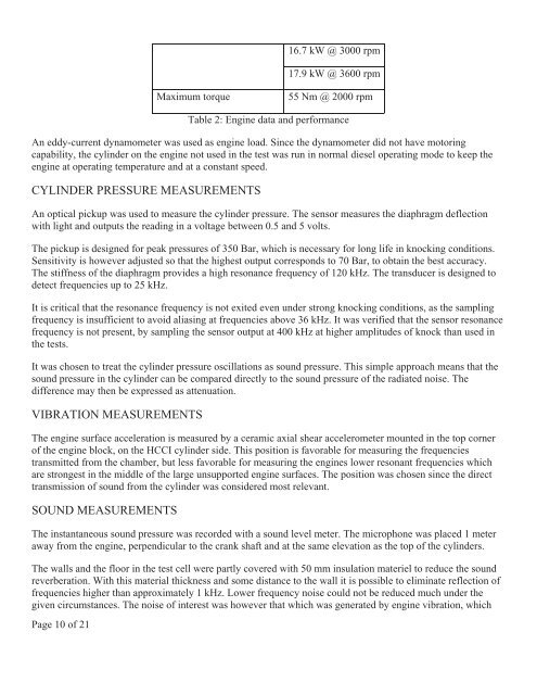
16.7 kW @ 3000 rpm<br />
17.9 kW @ 3600 rpm<br />
Maximum torque 55 Nm @ 2000 rpm<br />
Table 2: Engine data and performance<br />
An eddy-current dynamometer was used as engine load. Since the dynamometer did not have motoring<br />
capability, the cylinder on the engine not used in the test was run in normal diesel operating mode to keep the<br />
engine at operating temperature and at a constant speed.<br />
CYLINDER PRESSURE MEASUREMENTS<br />
An optical pickup was used to measure the cylinder pressure. The sensor measures the diaphragm deflection<br />
with light and outputs the reading in a voltage between 0.5 and 5 volts.<br />
The pickup is designed for peak pressures of 350 Bar, which is necessary for long life in knocking conditions.<br />
Sensitivity is however adjusted so that the highest output corresponds to 70 Bar, to obtain the best accuracy.<br />
The stiffness of the diaphragm provides a high resonance frequency of 120 kHz. The transducer is designed to<br />
detect frequencies up to 25 kHz.<br />
It is critical that the resonance frequency is not exited even under strong knocking conditions, as the sampling<br />
frequency is insufficient to avoid aliasing at frequencies above 36 kHz. It was verified that the sensor resonance<br />
frequency is not present, by sampling the sensor output at 400 kHz at higher amplitudes of knock than used in<br />
the tests.<br />
It was chosen to treat the cylinder pressure oscillations as sound pressure. This simple approach means that the<br />
sound pressure in the cylinder can be compared directly to the sound pressure of the radiated noise. The<br />
difference may then be expressed as attenuation.<br />
VIBRATION MEASUREMENTS<br />
The engine surface acceleration is measured by a ceramic axial shear accelerometer mounted in the top corner<br />
of the engine block, on the HCCI cylinder side. This position is favorable for measuring the frequencies<br />
transmitted from the chamber, but less favorable for measuring the engines lower resonant frequencies which<br />
are strongest in the middle of the large unsupported engine surfaces. The position was chosen since the direct<br />
transmission of sound from the cylinder was considered most relevant.<br />
SOUND MEASUREMENTS<br />
The instantaneous sound pressure was recorded with a sound level meter. The microphone was placed 1 meter<br />
away from the engine, perpendicular to the crank shaft and at the same elevation as the top of the cylinders.<br />
The walls and the floor in the test cell were partly covered with 50 mm insulation materiel to reduce the sound<br />
reverberation. With this material thickness and some distance to the wall it is possible to eliminate reflection of<br />
frequencies higher than approximately 1 kHz. Lower frequency noise could not be reduced much under the<br />
given circumstances. The noise of interest was however that which was generated by engine vibration, which


