

Troels Dyhr Pedersen.indd - Solid Mechanics
Troels Dyhr Pedersen.indd - Solid Mechanics
Troels Dyhr Pedersen.indd - Solid Mechanics

Create successful ePaper yourself
Turn your PDF publications into a flip-book with our unique Google optimized e-Paper software.
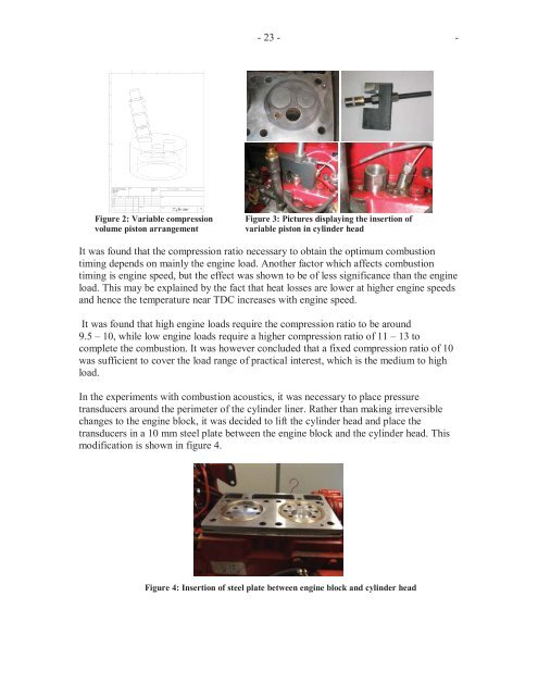
Figure 2: Variable compression<br />
volume piston arrangement<br />
- 23 - -<br />
Figure 3: Pictures displaying the insertion of<br />
variable piston in cylinder head<br />
It was found that the compression ratio necessary to obtain the optimum combustion<br />
timing depends on mainly the engine load. Another factor which affects combustion<br />
timing is engine speed, but the effect was shown to be of less significance than the engine<br />
load. This may be explained by the fact that heat losses are lower at higher engine speeds<br />
and hence the temperature near TDC increases with engine speed.<br />
It was found that high engine loads require the compression ratio to be around<br />
9.5 – 10, while low engine loads require a higher compression ratio of 11 – 13 to<br />
complete the combustion. It was however concluded that a fixed compression ratio of 10<br />
was sufficient to cover the load range of practical interest, which is the medium to high<br />
load.<br />
In the experiments with combustion acoustics, it was necessary to place pressure<br />
transducers around the perimeter of the cylinder liner. Rather than making irreversible<br />
changes to the engine block, it was decided to lift the cylinder head and place the<br />
transducers in a 10 mm steel plate between the engine block and the cylinder head. This<br />
modification is shown in figure 4.<br />
Figure 4: Insertion of steel plate between engine block and cylinder head


