Troels Dyhr Pedersen.indd - Solid Mechanics
Troels Dyhr Pedersen.indd - Solid Mechanics
Troels Dyhr Pedersen.indd - Solid Mechanics
You also want an ePaper? Increase the reach of your titles
YUMPU automatically turns print PDFs into web optimized ePapers that Google loves.
9 Heat release calculations<br />
- 27 - -<br />
9.1 The Heat Release analysis<br />
In order to visualize the rate of the combustion it is necessary to perform a heat release<br />
analysis. This analysis can provide the crank angle resolved rate of combustion.<br />
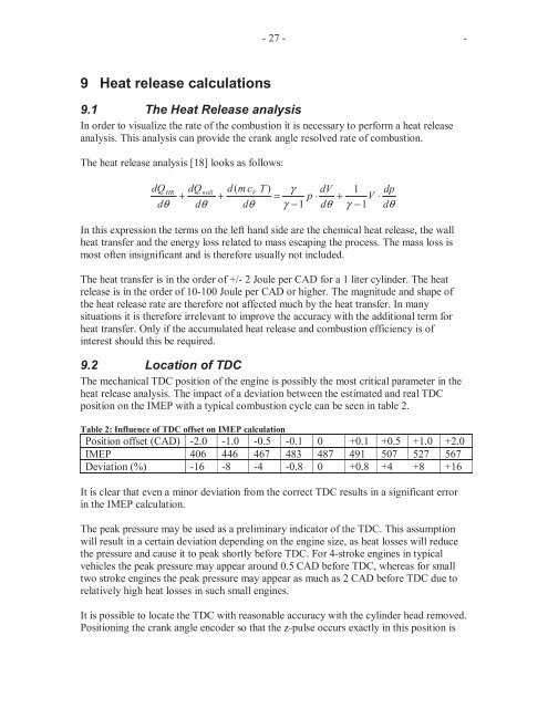
The heat release analysis [18] looks as follows:<br />
dQ V<br />
HR dQwall<br />
d(<br />
m c T ) γ dV 1 dp<br />
+ + = p ⋅ + V ⋅<br />
dθ<br />
dθ<br />
dθ<br />
γ − 1 dθ<br />
γ − 1 dθ<br />
In this expression the terms on the left hand side are the chemical heat release, the wall<br />
heat transfer and the energy loss related to mass escaping the process. The mass loss is<br />
most often insignificant and is therefore usually not included.<br />
The heat transfer is in the order of +/- 2 Joule per CAD for a 1 liter cylinder. The heat<br />
release is in the order of 10-100 Joule per CAD or higher. The magnitude and shape of<br />
the heat release rate are therefore not affected much by the heat transfer. In many<br />
situations it is therefore irrelevant to improve the accuracy with the additional term for<br />
heat transfer. Only if the accumulated heat release and combustion efficiency is of<br />
interest should this be required.<br />
9.2 Location of TDC<br />
The mechanical TDC position of the engine is possibly the most critical parameter in the<br />
heat release analysis. The impact of a deviation between the estimated and real TDC<br />
position on the IMEP with a typical combustion cycle can be seen in table 2.<br />
Table 2: Influence of TDC offset on IMEP calculation<br />
Position offset (CAD) -2.0 -1.0 -0.5 -0.1 0 +0.1 +0.5 +1.0 +2.0<br />
IMEP 406 446 467 483 487 491 507 527 567<br />
Deviation (%) -16 -8 -4 -0.8 0 +0.8 +4 +8 +16<br />
It is clear that even a minor deviation from the correct TDC results in a significant error<br />
in the IMEP calculation.<br />
The peak pressure may be used as a preliminary indicator of the TDC. This assumption<br />
will result in a certain deviation depending on the engine size, as heat losses will reduce<br />
the pressure and cause it to peak shortly before TDC. For 4-stroke engines in typical<br />
vehicles the peak pressure may appear around 0.5 CAD before TDC, whereas for small<br />
two stroke engines the peak pressure may appear as much as 2 CAD before TDC due to<br />
relatively high heat losses in such small engines.<br />
It is possible to locate the TDC with reasonable accuracy with the cylinder head removed.<br />
Positioning the crank angle encoder so that the z-pulse occurs exactly in this position is


