Biogas upgrading – Review of commercial technologies - SGC
Biogas upgrading – Review of commercial technologies - SGC
Biogas upgrading – Review of commercial technologies - SGC

You also want an ePaper? Increase the reach of your titles
YUMPU automatically turns print PDFs into web optimized ePapers that Google loves.
<strong>SGC</strong> Rapport 2013:270<br />
thane loss. It is also beneficial if methane in the <strong>of</strong>f-gas can be used in an efficient<br />
way by e.g. cogeneration in a boiler or CHP. The second design (ii) is used in<br />
most biogas <strong>upgrading</strong> units built with membranes from Air Liquide Medal TM . This<br />
design increases the methane recovery compared to design (i). In this case the<br />
permeate (the gas passing through the membrane) from the first membrane stage<br />
is removed from the system while the permeate from the second membrane stage<br />
is recirculated back to the compressor to minimize the methane slip. This will however<br />
increase the energy consumption. The third design (iii) is used with membranes<br />
from Evonik Sepuran®. The retentate (the gas not passing through the<br />
membrane) from the first stage is polished in the second membrane stage, in a<br />
similar way as in design (ii) to obtain a product gas <strong>of</strong> with a purity <strong>of</strong> more than<br />
97% methane. Additional to design (ii), also the permeate <strong>of</strong> the first stage is polished<br />
in a third membrane stage, to minimize the CH4 concentration in the <strong>of</strong>f-gas<br />
and the volume <strong>of</strong> gas circulated back to the compressor. The permeate stream <strong>of</strong><br />
the second stage and the retentate <strong>of</strong> the third stage are combined and recycled to<br />
the compressor.<br />
In a membrane unit, the main part <strong>of</strong> the remaining water after compression is<br />
separated from the biomethane together with the carbon dioxide. Therefore, a gas<br />
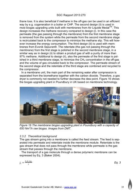
dryer is commonly not needed to further decrease the dew point. Figure 16 shows<br />
the biogas <strong>upgrading</strong> plant in Poundbury in UK based on membrane technology.<br />
Figure 16 The membrane biogas <strong>upgrading</strong> plant in Poundbury with a capacity <strong>of</strong><br />
650 Nm 3 /h raw biogas. Images from DMT.<br />
2.3.2 Theoretical background<br />
The gas stream going into a membrane is called the feed stream. The feed is separated<br />
into permeate and retentate inside the membrane module. Retentate is the<br />
gas stream that does not pass through the membrane while permeate is the gas<br />
stream that passes through the membrane.<br />
The transport <strong>of</strong> a gas molecule through a dense polymeric membrane can be<br />
expressed by Eq. 3 (Baker 2004).<br />
݆ = ∆ <br />
<br />
Eq. 3<br />
Svenskt Gastekniskt Center AB, Malmö <strong>–</strong> www.sgc.se 31