Biogas upgrading – Review of commercial technologies - SGC
Biogas upgrading – Review of commercial technologies - SGC
Biogas upgrading – Review of commercial technologies - SGC

Create successful ePaper yourself
Turn your PDF publications into a flip-book with our unique Google optimized e-Paper software.
<strong>SGC</strong> Rapport 2013:270<br />
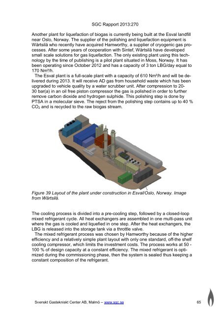
Another plant for liquefaction <strong>of</strong> biogas is currently being built at the Esval landfill<br />
near Oslo, Norway. The supplier <strong>of</strong> the polishing and liquefaction equipment is<br />
Wärtsilä who recently have acquired Hamworthy, a supplier <strong>of</strong> cryogenic gas processes.<br />
After some years <strong>of</strong> cooperation with Sintef, Wärtsilä have developed<br />
small scale solutions for gas liquefaction. The only existing plant using this technology<br />
by the time <strong>of</strong> publishing is a pilot plant situated in Moss, Norway. It has<br />
been operating since October 2012 and has a capacity <strong>of</strong> 3 ton LBG/day equal to<br />
170 Nm³/h.<br />
The Esval plant is a full-scale plant with a capacity <strong>of</strong> 610 Nm³/h and will be delivered<br />
during 2013. It will receive AD gas from household waste which has been<br />
upgraded to vehicle quality by a water scrubber unit. After compression to 20-<br />
30 bar(a) in an oil free piston compressor the gas is polished in order to further<br />
remove carbon dioxide and hydrogen sulphide. This polishing step is done by<br />
PTSA in a molecular sieve. The reject from the polishing step contains up to 40 %<br />
CO2 and is recycled to the raw biogas stream.<br />
Figure 39 Layout <strong>of</strong> the plant under construction in Esval/Oslo, Norway. Image<br />
from Wärtsilä.<br />
The cooling process is divided into a pre-cooling step, followed by a closed-loop<br />
mixed refrigerant cycle. All heat exchangers are assembled in one multi-pass unit<br />
where the gas is cooled and liquefied in one step. After the heat exchangers, the<br />
LBG is released into the storage tank via a throttle valve.<br />
The mixed refrigerant process was chosen by Hamworthy because <strong>of</strong> the higher<br />
efficiency and a relatively simple plant layout with only one standard, <strong>of</strong>f-the shelf<br />
cooling compressor, which limits the investment costs. The process works at 50 -<br />
100 % <strong>of</strong> design capacity at a constant efficiency. The mixed refrigerant is optimized<br />
during the commissioning phase, then the system is sealed thus keeping a<br />
constant composition <strong>of</strong> the refrigerant.<br />
Svenskt Gastekniskt Center AB, Malmö <strong>–</strong> www.sgc.se 65