3M & SUSS announce agreement on temporary wafer ... - I-Micronews
3M & SUSS announce agreement on temporary wafer ... - I-Micronews
3M & SUSS announce agreement on temporary wafer ... - I-Micronews

Create successful ePaper yourself
Turn your PDF publications into a flip-book with our unique Google optimized e-Paper software.
J U L Y 2 0 0 9 i s s u e n ° 1 1<br />
N e w s l e t t e r o n 3 D I C , T S V , W L P & E m b e d d e d T e c h n o l o g i e s<br />
C O M P A N Y P R O F I L E<br />
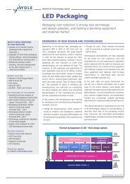
Fig 2 - Pictures of fruit taken, left, with a VGA resoluti<strong>on</strong> <strong>wafer</strong> level camera<br />
having a single optical element and, right, the 5MP camera <strong>on</strong> a producti<strong>on</strong><br />
model N95 cell ph<strong>on</strong>e. The cost differential between these two cameras,<br />
which is larger than an order of magnitude, is not immediately apparent in<br />
the image quality.<br />
YD: What are the main technical<br />
challenges to make WLC today? Can you<br />
comment where the pain points are?<br />
GH & BK: The principal technical challenges to<br />
making <strong>wafer</strong> level cameras are how to manufacture<br />
suitable lenses, combine these with other essential<br />
parts like apertures and filters, and then align and<br />
assemble these in a manner that yields an integrated<br />
optical comp<strong>on</strong>ent.<br />
Wafer level lenses are all made by replicati<strong>on</strong><br />
processes. While these are well known and<br />
understood and suitable equipment is available<br />
commercially, there is a major issue in that traditi<strong>on</strong>al<br />
optical polymers are wholly inadequate for <strong>wafer</strong><br />
level camera optics. Key attributes are optical<br />
performance, mouldability and compatibility with the<br />
thermal excursi<strong>on</strong> of the lead-free solder reflow<br />
cycle, typically 265°C for 2 minutes, x3 cycles. Wafer<br />
level cameras currently suffer from the problem that<br />
the volume of optical polymer required is insufficient<br />
for the chemical companies to justify investing in the<br />
development of new formulati<strong>on</strong>s. C<strong>on</strong>sequently the<br />
companies that have developed successful <strong>wafer</strong><br />
level optics technology have paid for the polymer<br />
development privately and all details about their<br />
chemistry properties and useage remain closely<br />
guarded trade secrets. This is clearly dem<strong>on</strong>strated<br />
by the lens slopes and sags. The optical design of<br />
<strong>wafer</strong> level cameras is limited by the achievable lens<br />
sag, which for commercial optical polymers and<br />
mastering techniques is around 200um [SSEC<br />
2009]. Higher values allow a camera module to<br />
maintain the same form factor but grow progressively<br />
in resoluti<strong>on</strong>. More than <strong>on</strong>e company is<br />
dem<strong>on</strong>strating lenses with >500um sag and >50<br />
degree slopes <strong>on</strong> pre-producti<strong>on</strong> samples for ><str<strong>on</strong>g>3M</str<strong>on</strong>g>P<br />
reflowable <strong>wafer</strong> level cameras.<br />
Early <strong>wafer</strong> level cameras were built to mirror<br />
discrete counterparts <strong>on</strong> a piece by piece basis. Now<br />
the optical trains are extremely complex, exhibiting<br />
double-sided lenses where each surface can be a<br />
different material and size with different profiles and<br />
coatings . To achieve this degree of sophisticati<strong>on</strong><br />
required a number of technical problems to be<br />
solved, including <strong>wafer</strong> bow after replicati<strong>on</strong>, lens<br />
figure error and lens dicing (the two key issues here<br />
being to ensuring the polymer lenses have adequate<br />
adhesi<strong>on</strong> to the substrate and the avoiding<br />
c<strong>on</strong>taminati<strong>on</strong> of the lens surface). As with the lens<br />
materials, there is little published informati<strong>on</strong> <strong>on</strong> the<br />
soluti<strong>on</strong>s, but that they have been solved is<br />
evidenced by product availability from more than <strong>on</strong>e<br />
source at pricing that is aggressively competitive<br />
with discrete manufacturing and assembly.<br />
Similarly, the technology for mastering of lenses for<br />
<strong>wafer</strong> level cameras has advanced to the point<br />
where can be d<strong>on</strong>e directly for a fully populated<br />
200mm <strong>wafer</strong> to the slope and sag specificati<strong>on</strong><br />
listed above. Previously masters had to be built<br />
using step-and-repeat or stitching methods, both of<br />
which give rise to alignment errors that are difficult to<br />
c<strong>on</strong>trol. Clearly, direct mastering is a far superior<br />
approach. Although the equipment to make large<br />
masters is commercially available, it is sold without<br />
the know-how to achieve the placement accuracy,<br />
profile deviati<strong>on</strong> and surface roughness necessary<br />
for camera lenses. This informati<strong>on</strong> is hard w<strong>on</strong> and<br />
closely guarded by the companies that specialise in<br />
making lens masters.<br />
The optical train of a camera module c<strong>on</strong>sists of<br />
more than just lenses. To functi<strong>on</strong> correctly it must<br />
also c<strong>on</strong>tain, apertures, baffles, pupils and antireflecti<strong>on</strong><br />
coatings to name a few. All of these<br />
comp<strong>on</strong>ents can be realised with semic<strong>on</strong>ductor<br />
processing techniques at the <strong>wafer</strong> level.<br />
Assembly of optical comp<strong>on</strong>ents in a stack requires<br />
precise alignment in plane, rotati<strong>on</strong> and tilt. The<br />
alignment accuracy is limited to the equipment<br />
capability, which is barely adequate for optical<br />
applicati<strong>on</strong>s. The requirement is for fr<strong>on</strong>t-to-back<br />
alignment of lenses fabricated <strong>on</strong> each side of a<br />
single substrate and <strong>wafer</strong>-to-<strong>wafer</strong> alignment to<br />
fabricate the camera module at the <strong>wafer</strong> level. Two<br />
complementary approaches are used to solve this<br />
problem. The first is good optics design, which takes<br />
into account the limitati<strong>on</strong>s of the equipment. For<br />
example good practice is to set the focus depth<br />
between the lens stack and imager to larger than the<br />
equipment 3 sigma metric. However this imposes<br />
c<strong>on</strong>straints <strong>on</strong> other aspects of the optical<br />
performance of the design, which is not always<br />
desirable. Accordingly, great attenti<strong>on</strong> is being paid<br />
to techniques for getting the best possible<br />
performance from the assembly equipment. One<br />
exhibiting great promise is innovati<strong>on</strong> in optical<br />
alignment marks, which are, of course, easily<br />
integrated with a <strong>wafer</strong> of optical elements. Another<br />
approach is active alignment. Commercial equipment<br />
capable of active alignment is too slow and too<br />
expensive to be used for assembly of <strong>wafer</strong> level<br />
cameras. The c<strong>on</strong>tract assembly companies have<br />
invested heavily in proprietary active alignment tools<br />
to the extent that a complete lens stack can be built<br />
and integrated with an imager using active alignment<br />
for each level of assembly including full-field<br />
measurement of MTF, taking <strong>on</strong>ly sec<strong>on</strong>ds per part.<br />
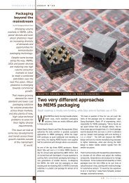
Fig 3 – Breakdown of cost for a discrete and a <strong>wafer</strong> level VGA camera module, normalised to the cost of the discrete imager die. The <strong>wafer</strong> level camera module<br />
is not <strong>on</strong>ly cheaper but there are further c<strong>on</strong>siderable savings to be gained when the module is integrated in the product by a simple solder reflow cycle, together<br />
with all the other surface mount comp<strong>on</strong>ents.<br />
Printed <strong>on</strong> recycled paper<br />
7