20111104_CN.12_complete_UK_LOW.pdf

Create successful ePaper yourself
Turn your PDF publications into a flip-book with our unique Google optimized e-Paper software.
tools and accessories for crimp contacts<br />
The crimping concept<br />
The crimp connection is an irreversible connection between one or two<br />
conductors and a crimp contact. The crimp connection is obtained by pinching<br />
or pressing the contact metal - or shaft - firmly with the crimping tool.<br />
A good crimp connection is provided by a suitable combination between the<br />
crimping base, the crimping part of the contact metal, i.e. the crimp contact,<br />
firmly with and the section of the conductor.<br />
These comments refer to crimped connections carried out with copper<br />
flexible conductors in class 5 (flexible) or 6 (extra flexible) according to<br />
standards IEC 60228 and IEC 60228-A (Italian standard CEI 20-29).<br />
Solid copper conductors (class 1) or in other materials (aluminium , iron,<br />
etc) often require special precautions for contacts and for crimping tools, to<br />
be agreed with the manufacturer.<br />
The main technical advantages provided by crimping connections over<br />
soldered connections are:<br />
- The process does not use heat and does not require materials.<br />
- Perfect connection is acquired that is intrinsic with cold soldering.<br />
- No degradation of the elastic characteristics of the female contacts (a<br />
problem that arises with soldering temperatures).<br />
- No health risks connected with the use of heavy metals or fumes<br />
generated from the soldering process.<br />
- Preservation of the conductor's flexibility immediately upon connection.<br />
- No conductors with burned, discoloured or overheated insulating material.<br />
- Excellent reproducibility of the performances of the electrical and<br />
mechanical connections.<br />
- facilitated production controls.<br />
Other advantages obtained by crimping connections over screw terminal<br />
connections are:<br />
- Less drop of currency in the connector contacts.<br />
- High stability in time even in the presence of vibrations.<br />
- High duration in presence of corrosion (gastight).<br />
- Individual insertion of the contacts in the connector (it is possible to<br />
eliminate unnecessary contacts).<br />
- Less time required for connection.<br />
- Possibility of pre-production of the terminated conductors with crimp<br />
contacts.<br />
- Easy substitution of individual contacts during maintenance.<br />
- Possibility of selectively isolating the circuits during maintenance via the<br />
extraction of the contacts from the connector.<br />
The crimped connections for wire sections up to 10 mm 2 are covered by the<br />
EN 60352-2:2006 European standard equivalent to the IEC 60352-2 Issue<br />
2 (2006-02) international standard.<br />
The EN 60352-2 standard also includes a practical guide, which lists the<br />
following main points.<br />
The quality of a crimped connection is mainly affected by the quality of<br />
materials used and by the condition of the crimp contact (in particular the<br />
crimp shaft) and wire surfaces.<br />
To ensure a good quality crimped connection, an essential parameter is the<br />
wire mechanical retention in the contact.<br />
The standard makes a distinction between the closed crimp shaft, inherently<br />
stronger, and the open crimp shaft. ILME crimp contacts are closed crimp<br />
shaft contacts, with inspection hole which ensures a higher mechanical<br />
performance compared to the open shaft crimp contacts, such as better<br />
mechanical sturdiness and stability during operation.<br />
They have been machine turned, thus ensuring a better electrical<br />
performance (better conductivity).<br />
2002 Amendment 2 of the previous IEC standard issue controversially<br />
unified the minimum resistance to tensile stress values established for open<br />
shaft contacts (curve B of old Figure 5) and closed shaft contacts (curve A<br />
of old Figure 5) by lowering them to the values (shown in curve B), which<br />
can be achieved by open shaft crimp contacts. This has controversially<br />
relaxed the suitability requirements both for closed crimp shaft, typically<br />
large, machine turned and for crimp tools specially made for these contacts.<br />
Several industries continue to prefer the higher performance ensured by<br />
closed shaft crimp contacts, the only ones to ensure the higher resistance<br />
to tensile stress values believed to be essential for the most demanding<br />
industrial applications.<br />
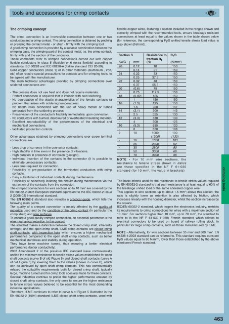
Therefore, ILME continues to refer to curve A of Figure 5 illustrated in the<br />
EN 60352-2 (1994) standard: ILME closed shaft crimp contacts, used with<br />
flexible copper wires, featuring a section included in the ranges shown and<br />
correctly crimped with the recommended tools, ensure breakage resistant<br />
connections at least equal to the values shown in the table shown below<br />
(for reference, the corresponding R t /S unified tensile stress load value is<br />
also shown [N/mm 2 ]).<br />
Section S Resistance to R t /S<br />
traction R t<br />
AWG mm 2 (N) (N/mm 2 )<br />
26 0.12 18 150<br />
- 0.14 21 150<br />
24 0.22 33 150<br />
- 0.25 37.5 150<br />
22 0.32 48 150<br />
- 0.37 55.5 150<br />
20 (0.6) 75 150<br />
- 0.75 112.5 150<br />
18 (0.82) 125 150<br />
- 1 150 150<br />
16 (1.3) 195 150<br />
- 1.5 220 147<br />
14 (2.1) 300 143<br />
- 2.5 325 130<br />
12 (3.3) 430 130<br />
- 4 500 125<br />
10 (5.3) 635 120<br />
- 6 650 108<br />
7 10 1000 100<br />
(1300) (130)<br />
- 16 1650 103<br />
- 25 2300 92<br />
- 35 2800 80<br />
50 3300 66<br />
- 70 3900 56<br />
NOTE - For 10 mm 2 wire sections, the<br />
resistance to tensile stress shown in italics<br />
are those specified in the NF F 61-030<br />
standard (for 10 mm 2 , the value in brackets)<br />
The basic criteria used for the resistance to tensile stress values required<br />
by EN 60352-2 standard is that such resistance is at least equal to 60% of<br />
the breakage unified load of the same annealed copper wire.<br />
This applies to wire sections up to about 1.5 mm 2 ; above this section, the<br />
ratio is slightly lower as retention is also affected by friction, which<br />
increases linearly with the housing diameter, whilst the section increases by<br />
the square.<br />
IEC/EN 60352-2 standard, which targets the electronics industry, restricts<br />
its requirements to crimp connections for wires with a maximum section of<br />
10 mm 2 . For sections higher than 10 mm 2 , up to 70 mm 2 , the standard to<br />
refer to is the NF F 61-030 (1989) French standard which relates to<br />
electrical connectors to be used on board of railway rolling stock, in<br />
particular for large crimp contacts, such as those manufactured by ILME.<br />
NOTE - Alternatively, for wire sections between 35 mm 2 and 300 mm 2 , EN<br />
61238-1:2003 standard can be referred to. This standard requires constant<br />
R t /S values equal to 60 N/mm 2 , lower than those established by the above<br />
mentioned French standard.<br />
463<br />
crimping tools