- Page 1 and 2:
Multipole connectors for industrial
- Page 3 and 4:
general index introduction to the c
- Page 5 and 6:
general enclosure index C-TYPE size
- Page 7 and 8: IMPORTANT NOTES ILME designs and ma
- Page 9 and 10: general overview MIXO series insert
- Page 11 and 12: connector guide CHOOSE YOUR CONNECT
- Page 13 and 14: general overview of the multipole c
- Page 15 and 16: general features of multipole conne
- Page 17 and 18: standards - connector inside a pane
- Page 19 and 20: standards Determination of creepage
- Page 21 and 22: general overview of the multipole c
- Page 23 and 24: insert features for multipole conne
- Page 25 and 26: insert features for multipole conne
- Page 27 and 28: insert features for multipole conne
- Page 29 and 30: insert features for multipole conne
- Page 31 and 32: conductor connections CSH Series Co
- Page 33 and 34: conductor connections removable cri
- Page 35 and 36: enclosure versions and applications
- Page 37 and 38: enclosure versions and applications
- Page 39 and 40: Web site The technical features of
- Page 41 and 42: Enclosures and inserts combinations
- Page 43 and 44: CKS 3 and 4 poles + m 10A - 400V en
- Page 45 and 46: CK...RY 3 and 4 poles + m 10A - 250
- Page 47 and 48: CD 7 poles + m 10A - 250V enclosure
- Page 49 and 50: CD 15 poles + m 10A - 250V enclosur
- Page 51 and 52: CD 40 poles + m 10A - 250V enclosur
- Page 53 and 54: CD 64 poles + m 10A - 250V enclosur
- Page 55 and 56: CD 128 poles + m 10A - 250V enclosu
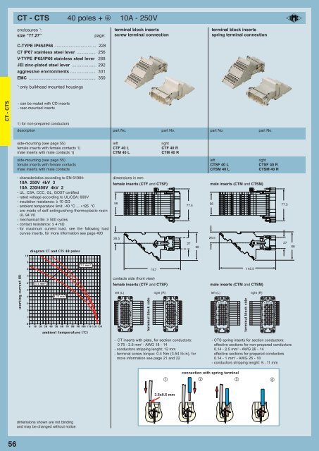
- Page 57: CT - CTS inserts with incorporated
- Page 61 and 62: CDD 24 poles + m 10A - 250V enclosu
- Page 63 and 64: CDD 42 poles + m 10A - 250V enclosu
- Page 65 and 66: CDD 76 poles + m 10A - 250V enclosu
- Page 67 and 68: CDD 144 poles + m 10A - 250V enclos
- Page 69 and 70: CQ 12 poles + m coding positions fo
- Page 71 and 72: CQ 5 poles + m 16A - 230/400V enclo
- Page 73 and 74: CQ 4 poles (40A - 400/690V) + 2 pol
- Page 75 and 76: CDC 10 poles + m 16A - 250V enclosu
- Page 77 and 78: CDC 16 poles + m 16A - 250V enclosu
- Page 79: CDC 32 poles + m 16A - 250V enclosu
- Page 82 and 83: CQE 80 CQE 10 poles + m 16A - 500V
- Page 84 and 85: CQE 82 CQE 32 poles + m 16A - 500V
- Page 86 and 87: CQE 84 CQE 64 poles + m 16A - 500V
- Page 88 and 89: CSH 86 introduction As an improveme
- Page 90 and 91: CSH 88 CSH 6 poles + m 16A - 500V e
- Page 92 and 93: CSH 90 CSH 16 poles + m 16A - 500V
- Page 94 and 95: CSH 92 CSH 32 poles + m 16A - 500V
- Page 96 and 97: CCE 94 CCE 6 poles + m 16A - 500V e
- Page 98 and 99: CCE 96 CCE 10 poles + m 16A - 500V
- Page 100 and 101: CCE 98 CCE 16 poles + m 16A - 500V
- Page 102 and 103: CCE 100 CCE 24 poles + m 16A - 500V
- Page 104 and 105: CCE 102 CCE 32 poles + m 16A - 500V
- Page 106 and 107: CCE 104 CCE 48 poles + m 16A - 500V
- Page 108 and 109:
JCNE - JCSE 106 enclosures: size
- Page 110 and 111:
JCNE - JCSE 108 enclosures: size
- Page 112 and 113:
JCNE - JCSE 110 enclosures: size
- Page 114 and 115:
CNE...RY 112 CNE...RY 6 poles + m 1
- Page 116 and 117:
CNE...RY 114 CNE...RY 16 poles + m
- Page 118:
CNE...RY 116 CNE...RY 48 poles + m
- Page 121 and 122:
CSS 10 poles + m 16A - 500V enclosu
- Page 123 and 124:
CSS 24 poles + m 16A - 500V enclosu
- Page 125 and 126:
CSS 48 poles + m 16A - 500V enclosu
- Page 127 and 128:
CTE - CTSE - CT inserts with incorp
- Page 129 and 130:
CTE - CTSE 10 poles + m 16A - 500V
- Page 131 and 132:
CTE - CTSE 24 poles + m 16A - 500V
- Page 133 and 134:
CT 10 poles + m 16A - 400V enclosur
- Page 135 and 136:
CT 24 poles + m 16A - 400V enclosur
- Page 137 and 138:
CME - CMSE 3 + 2 (aux) poles + m 16
- Page 139 and 140:
CME - CMSE 6 + 2 (aux) poles + m 16
- Page 141 and 142:
CME - CMSE 10 + 2 (aux) poles + m 1
- Page 143 and 144:
CME - CMSE 12 + 4 (aux) poles + m 1
- Page 145 and 146:
CME - CMSE 20 + 4 (aux) poles + m 1
- Page 147 and 148:
CME 16 + 2 (aux) poles + m 16A - 40
- Page 149:
CME 32 + 4 (aux) poles + m 16A - 40
- Page 152 and 153:
CP 150 CP 12 poles + m 35A - 400/69
- Page 154 and 155:
CX 152 CX 6 poles (40A - 690V) + 36
- Page 156 and 157:
CX 154 CX 4 poles (80A - 690V) + m
- Page 158 and 159:
MIXO 156 MIXO modular units for mul
- Page 160 and 161:
MIXO 158 MIXO modular units for mul
- Page 162 and 163:
MIXO 160 MIXO modular units 1 pole
- Page 164 and 165:
MIXO 162 main features MIXO CX..G 1
- Page 166 and 167:
MIXO 164 MIXO modular units 2 poles
- Page 168 and 169:
MIXO main features MIXO CX 3/4 XD m
- Page 170 and 171:
MIXO 168 MIXO modular units 3 poles
- Page 172 and 173:
MIXO 170 main features MIXO CX 4 X
- Page 174 and 175:
MIXO 172 MIXO modular units 6 poles
- Page 176 and 177:
MIXO 174 MIXO modular units 20 pole
- Page 178 and 179:
MIXO 176 MIXO modular units HT 2 po
- Page 180 and 181:
MIXO 178 MIXO modular units 17 pole
- Page 182 and 183:
MIXO 180 MIXO modular units 1 or 4
- Page 184 and 185:
MIXO 182 MIXO modular units 1 pole
- Page 186 and 187:
MIXO 184 MIXO modular units for 2 R
- Page 188 and 189:
MIXO 186 MIXO modular units for 9-p
- Page 190 and 191:
MIXO MIXO modular inserts for multi
- Page 192 and 193:
MIXO 190 MIXO modular units for coa
- Page 194 and 195:
MIXO 192 MIXO modular units accesso
- Page 196 and 197:
MIXO 194 MIXO frames for modular un
- Page 198 and 199:
C-TYPE - metallic - CLASS rotative
- Page 200 and 201:
standards 198 ENCLOSURE CHARACTERIS
- Page 202 and 203:
C-TYPE - grandezza 32.13 200 combin
- Page 204 and 205:
C-TYPE - size 21.21 202 CK and MK e
- Page 206 and 207:
C-TYPE - size 21.21 204 CK and MK e
- Page 208 and 209:
C-TYPE - size 32.13 CQ enclosures s
- Page 210 and 211:
C-TYPE - size 49.16 208 CZ and MZ e
- Page 212 and 213:
C-TYPE - size 49.16 210 CZ and MZ e
- Page 214 and 215:
C-TYPE - size 66.16 212 CZ and MZ e
- Page 217 and 218:
CH - CA and MH - MA enclosures size
- Page 219 and 220:
CH - CA and MH - MA enclosures size
- Page 221 and 222:
CH - CA and MH - MA enclosures size
- Page 223 and 224:
CH - CA and MH - MA enclosures size
- Page 225 and 226:
CH - CA and MH - MA enclosures size
- Page 227 and 228:
CH - CA and MH - MA enclosures size
- Page 229 and 230:
CH - CA and MH - MA enclosures size
- Page 231 and 232:
CH - CA and MH - MA enclosures size
- Page 233 and 234:
CH - CA and MH - MA enclosures size
- Page 235 and 236:
CH - CA and MH - MA enclosures size
- Page 237 and 238:
235
- Page 239 and 240:
CH - CA and MH - MA enclosures size
- Page 241 and 242:
CH - CA and MH - MA enclosures size
- Page 243 and 244:
CQ and MQ - CZAC and CACsize “104
- Page 245 and 246:
CH - CA and MH - MA enclosures size
- Page 247 and 248:
CH and MH enclosures size “77.62
- Page 249 and 250:
CH and MH enclosures size “77.62
- Page 251 and 252:
IP67
- Page 253 and 254:
enclosures with IP67 V-Type closure
- Page 255 and 256:
IP67 V-Type enclosure closing movem
- Page 257 and 258:
C7 - C7A and M7 - M7A IP67 enclosur
- Page 259 and 260:
C7 - C7A and M7 - M7A IP67 enclosur
- Page 261 and 262:
accessories for multiple connectors
- Page 263 and 264:
CV - CVA and MV - MVA enclosures si
- Page 266 and 267:
V-TYPE - size 57.27 264 CV enclosur
- Page 268 and 269:
V-TYPE - size 57.27 266 CV - CVA an
- Page 270 and 271:
V-TYPE - size 77.27 268 CV enclosur
- Page 272 and 273:
V-TYPE - size 77.27 270 CV - CVA an
- Page 274 and 275:
V-TYPE - size 104.27 272 CV enclosu
- Page 276 and 277:
V-TYPE - size 104.27 274 CV - CVA a
- Page 280 and 281:
T-TYPE - overview 278 characteristi
- Page 282 and 283:
T-TYPE - overview introduction New
- Page 284 and 285:
T-TYPE - size 44.27 282 TC - TM enc
- Page 286 and 287:
T-TYPE - size 77.27 284 TC - TM enc
- Page 290 and 291:
JEI - size 44.27 288 JCV enclosures
- Page 292 and 293:
JEI - size 57.27 290 JCV enclosures
- Page 294 and 295:
JEI - size 77.27 292 JCV enclosures
- Page 296 and 297:
JEI - size 104.27 294 JCV enclosure
- Page 298 and 299:
BIG - overview BIG 296
- Page 300 and 301:
BIG - overview BIG Enclosures The s
- Page 302 and 303:
BIG - overview Simplified wiring Co
- Page 304 and 305:
BIG - overview Range The new items
- Page 306 and 307:
BIG - size 44.27 304 CB - MB BIG en
- Page 308 and 309:
BIG - size 44.27 306 CB - MB BIG en
- Page 310 and 311:
BIG - size 57.27 308 CB - MB BIG en
- Page 312 and 313:
BIG - size 57.27 310 CB - MB BIG en
- Page 314 and 315:
BIG - size 77.27 312 CB - MB BIG en
- Page 316 and 317:
BIG - size 77.27 314 CB - MB BIG en
- Page 318 and 319:
BIG - size 104.27 316 CB - MB BIG e
- Page 320 and 321:
BIG - size 104.27 318 CB - MB BIG e
- Page 322 and 323:
V-TYPE - V-Type enclosures 320 C7 -
- Page 325 and 326:
enclosures for aggressive environme
- Page 327 and 328:
CK and MK enclosures size “21.21
- Page 329 and 330:
CK and MK enclosures size “66.16
- Page 331 and 332:
CH - CA and MH - MA enclosures size
- Page 333 and 334:
CH - CA and MH - MA enclosures size
- Page 335 and 336:
CH and MH enclosures size “77.62
- Page 337 and 338:
EMC connectors and electromagnetic
- Page 339 and 340:
EMC connectors and electromagnetic
- Page 341 and 342:
EMC connectors and electromagnetic
- Page 343 and 344:
EMC connectors and electromagnetic
- Page 345 and 346:
CK and MK enclosures size “21.21
- Page 347 and 348:
CQ enclosures size “32.13” EMC
- Page 349 and 350:
CZ and MZ enclosures size “66.16
- Page 351 and 352:
CH - CA and MH - MA enclosures size
- Page 353 and 354:
CH - CA and MH - MA enclosures size
- Page 355 and 356:
CK and MK enclosures size “21.21
- Page 357 and 358:
CH - CA and MH - MA enclosures size
- Page 359 and 360:
CH - CA and MH - MA enclosures size
- Page 361 and 362:
characteristics Description CENTRAL
- Page 363 and 364:
CA and MA enclosures size “44.27
- Page 365 and 366:
CA and MA enclosures size “57.27
- Page 367 and 368:
CA and MA enclosures size “77.27
- Page 369 and 370:
CA and MA enclosures size “104.27
- Page 372 and 373:
IP68 - overview general characteris
- Page 374 and 375:
special enclosures 372 CG - MG encl
- Page 376 and 377:
special enclosures 374 CG - MG encl
- Page 378 and 379:
special enclosures 376 CG - MG encl
- Page 380 and 381:
special enclosures 378 CG - MG encl
- Page 382 and 383:
special enclosures 380 CG - MG encl
- Page 384 and 385:
special enclosures 382 CG - MG encl
- Page 386 and 387:
special enclosures 384 CG - MG encl
- Page 388 and 389:
special enclosures 386 CG - MG encl
- Page 390 and 391:
special enclosures 388 CG - MG encl
- Page 392 and 393:
special enclosures 390 CG - MG encl
- Page 394 and 395:
830V - size 57.27 392 CM - CMA and
- Page 396 and 397:
830V - size 57.27 394 CM - CMA and
- Page 398 and 399:
396
- Page 400 and 401:
830V - size 77.27 398 CM - CMA and
- Page 402 and 403:
830V - size 77.27 400 CM - CMA and
- Page 405 and 406:
CM - CMA and MM - MMA enclosures si
- Page 407 and 408:
CM - CMA and MM - MMA enclosures si
- Page 409 and 410:
CM - CMA and MM - MMA enclosures si
- Page 411 and 412:
COB panel supports for multipole co
- Page 413 and 414:
COB panel supports for multipole co
- Page 415 and 416:
CZAC and CAC enclosures for special
- Page 417 and 418:
CMAN enclosures enclosures for spec
- Page 419 and 420:
CYG enclosures for special applicat
- Page 421:
CYG special design enclosures enclo
- Page 424 and 425:
accessories 422 complements and acc
- Page 426 and 427:
accessories 424 accessories for mul
- Page 428 and 429:
accessories 426 accessories for mul
- Page 430 and 431:
accessories 428 accessories for mul
- Page 432 and 433:
accessories 430 accessories for mul
- Page 434 and 435:
accessories 432 accessories for mul
- Page 436 and 437:
accessories 434 CR bridges for delt
- Page 438 and 439:
accessories 436 accessories for mul
- Page 440 and 441:
accessories 438 accessories for mul
- Page 442 and 443:
accessories 440 accessories for mul
- Page 444 and 445:
accessories 442 CJ RJ45 connector A
- Page 446 and 447:
accessories 444 adaptor inserts 1 s
- Page 448 and 449:
accessories 446 adaptor inserts 1 s
- Page 450:
attenuation 448 coaxial connectors
- Page 453 and 454:
DESINA main features Hybrid socket
- Page 455 and 456:
DESINA main features 1.6 Self-extin
- Page 457 and 458:
DESINA feature of inserts for multi
- Page 459 and 460:
CXL 2 pole fibre optics + 4 poles 1
- Page 461 and 462:
CK and MK enclosures size “21.21
- Page 463:
CK and MK enclosures size “21.21
- Page 466 and 467:
crimping tools 464 tools and access
- Page 468 and 469:
crimping tools 466 tools and access
- Page 470 and 471:
crimping tools 468 tools and access
- Page 472 and 473:
crimping tools 470 tools and access
- Page 474 and 475:
crimping tools 472 tools and access
- Page 476 and 477:
crimping tools 474 tools and access
- Page 478 and 479:
crimping tools 476 tools and access
- Page 480 and 481:
crimping tools 478 tools and access
- Page 482 and 483:
crimping tools 480 tools and access
- Page 484 and 485:
crimping tools 482 tools and access
- Page 486 and 487:
crimping tools tools and accessorie
- Page 488 and 489:
crimping tools 486 tools and access
- Page 490 and 491:
crimping tools 488 tools and access
- Page 492 and 493:
crimping tools 490 tools and access
- Page 494 and 495:
load curves 492 limit current curve
- Page 496 and 497:
load curves 494 limit current curve
- Page 498 and 499:
load curves 496 limit current curve
- Page 500 and 501:
load curves 498 limit current curve
- Page 502 and 503:
load curves 500 limit current curve
- Page 504 and 505:
Part Nos. index 502 Part Nos. index
- Page 506 and 507:
Part Nos. index 504 Part Nos. index
- Page 508 and 509:
Part Nos. index 506 Part Nos. index
- Page 510 and 511:
Part Nos. index 508 Part Nos. index
- Page 512 and 513:
Part Nos. index 510 Part Nos. index
- Page 514 and 515:
Part Nos. index 512 Part Nos. index
- Page 516 and 517:
Part Nos. index 514 Part Nos. index
- Page 518 and 519:
Notes