Insurance Discount May Pay for Your BPPP Training - American ...
Insurance Discount May Pay for Your BPPP Training - American ...
Insurance Discount May Pay for Your BPPP Training - American ...

You also want an ePaper? Increase the reach of your titles
YUMPU automatically turns print PDFs into web optimized ePapers that Google loves.
www.bonanza.org<br />
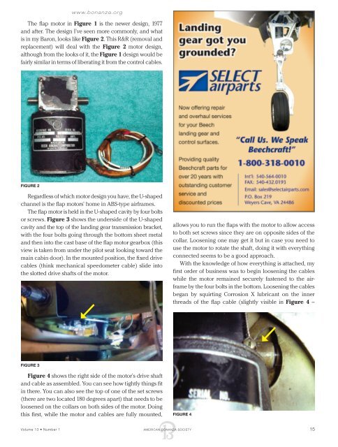
The flap motor in Figure 1 is the newer design, 1977<br />
and after. The design I’ve seen more commonly, and what<br />
is in my Baron, looks like Figure 2. This R&R (removal and<br />
replacement) will deal with the Figure 2 motor design,<br />
although from the looks of it, the Figure 1 design would be<br />
fairly similar in terms of liberating it from the control cables.<br />
Figure 2<br />
Regardless of which motor design you have, the U-shaped<br />
channel is the flap motors’ home in ABS-type airframes.<br />
The flap motor is held in the U-shaped cavity by four bolts<br />
or screws. Figure 3 shows the underside of the U-shaped<br />
cavity and the top of the landing gear transmission bracket,<br />
with the four bolts going through the bottom sheet metal<br />
and then into the cast base of the flap motor gearbox (this<br />
view is taken from under the pilot seat looking toward the<br />
main cabin door). In the mounted position, the fixed drive<br />
cables (think mechanical speedo meter cable) slide into<br />
the slotted drive shafts of the motor.<br />
allows you to run the flaps with the motor to allow access<br />
to both set screws since they are on opposite sides of the<br />
collar. Loosening one may get it but in case you need to<br />
use the motor to rotate the shaft, doing it with everything<br />
connected seems to be a good approach.<br />
With the knowledge of how everything is attached, my<br />
first order of business was to begin loosening the cables<br />
while the motor remained securely fastened to the airframe<br />
by the four bolts in the bottom. Loosening the cables<br />
began by squirting Corrosion X lubricant on the inner<br />
threads of the flap cable (slightly visible in Figure 4 –<br />
Figure 3<br />
Figure 4 shows the right side of the motor’s drive shaft<br />
and cable as assembled. You can see how tightly things fit<br />
in there. You can also see the top of one of the set screws<br />
(there are two located 180 degrees apart) that needs to be<br />
loosened on the collars on both sides of the motor. Doing<br />
this first, while the motor and cables are fully mounted,<br />
Figure 4<br />
Volume 13 • Number 1 AMERICAN BONANZA SOCIETY 15