H.264 Network DVR User Manual - Supercircuits Inc.
H.264 Network DVR User Manual - Supercircuits Inc.
H.264 Network DVR User Manual - Supercircuits Inc.

You also want an ePaper? Increase the reach of your titles
YUMPU automatically turns print PDFs into web optimized ePapers that Google loves.
SECTION 3: CONNECTIONS AND SETUP<br />
2. Connect the RJ11 cable to the <strong>DVR</strong>.<br />
a. If an RS485 port is present on the <strong>DVR</strong> back panel (DMR41DVD, DMR42DVD only):<br />
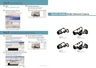
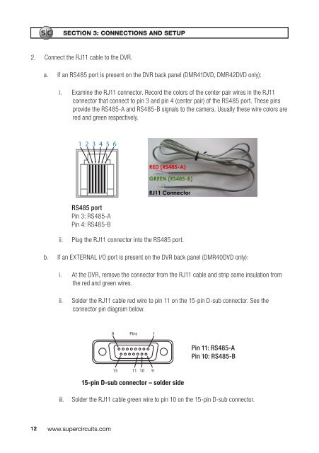
i. Examine the RJ11 connector. Record the colors of the center pair wires in the RJ11<br />
connector that connect to pin 3 and pin 4 (center pair) of the RS485 port. These pins<br />
provide the RS485-A and RS485-B signals to the camera. Usually these wire colors are<br />
red and green respectively.<br />
1 2 3 4 5 6<br />
RS485 port<br />
Pin 3: RS485-A<br />
Pin 4: RS485-B<br />
ii.<br />
Plug the RJ11 connector into the RS485 port.<br />
b. If an EXTERNAL I/O port is present on the <strong>DVR</strong> back panel (DMR40DVD only):<br />
i. At the <strong>DVR</strong>, remove the connector from the RJ11 cable and strip some insulation from<br />
the red and green wires.<br />
ii.<br />
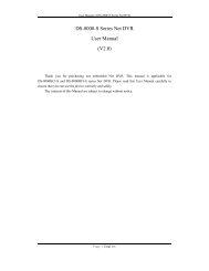
Solder the RJ11 cable red wire to pin 11 on the 15-pin D-sub connector. See the<br />
connector pin diagram below.<br />
8<br />
Pins<br />
1<br />
Pin 11: RS485-A<br />
Pin 10: RS485-B<br />
15 11 10<br />
9<br />
15-pin D-sub connector – solder side<br />
iii.<br />
Solder the RJ11 cable green wire to pin 10 on the 15-pin D-sub connector.<br />
12 www.supercircuits.com