H.264 Network DVR User Manual - Supercircuits Inc.
H.264 Network DVR User Manual - Supercircuits Inc.
H.264 Network DVR User Manual - Supercircuits Inc.

Create successful ePaper yourself
Turn your PDF publications into a flip-book with our unique Google optimized e-Paper software.
<strong>H.264</strong> <strong>Network</strong> <strong>DVR</strong><br />
<strong>User</strong> <strong>Manual</strong><br />
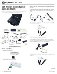
Product: DMR40DVD, DMR41DVD, DMR42DVD<br />
Please read this manual before using your recorder, and always follow the<br />
instructions for safety and proper use. Save this manual for future reference.<br />
DMR40-41-42DVD_RM
!<br />
WARNING<br />
Do not expose this product to liquids. Objects filled with liquids, such as vases, should be<br />
kept away.<br />
<br />
CAUTION<br />
This is a Safety Class 1 Product (provided with a protective earth ground incorporated<br />
in the power cord). The mains plug must be inserted in a electrical outlet provided with<br />
a protective earth contact. A break in the protective conductor inside or outside of the<br />
product can be dangerous. Tampering with the protective earth ground circuit is prohibited.<br />
This product complies with radio interference requirements.<br />
LEGAL NOTICE<br />
<strong>Supercircuits</strong> products are designed to meet safety and performance standards with the use of specific<br />
<strong>Supercircuits</strong> authorized accessories. <strong>Supercircuits</strong> disclaims liability associated with the use of non-<br />
<strong>Supercircuits</strong> authorized accessories.<br />
The recording, transmission, or broadcast of any person’s voice without their consent or a court order is<br />
strictly prohibited by law.<br />
<strong>Supercircuits</strong> makes no representations concerning the legality of certain product applications such as<br />
the making, transmission, or recording of video and/or audio signals of others without their knowledge<br />
and/or consent. We encourage you to check and comply with all applicable local, state, and federal laws<br />
and regulations before engaging in any form of surveillance or any transmission of radio frequencies.<br />
Other trademarks and trade names may be used in this document to refer to either the entities claiming<br />
the marks and names or their products. <strong>Supercircuits</strong>, <strong>Inc</strong>. disclaims any proprietary interest in<br />
trademarks and trade names other than its own.<br />
No part of this document may be reproduced or distributed in any form or by any means without the<br />
express written permission of <strong>Supercircuits</strong>, <strong>Inc</strong>.<br />
© 2010 <strong>Supercircuits</strong>, <strong>Inc</strong>. All rights reserved.<br />
11000 N. Mopac Expressway, Building 300, Austin, TX 78759<br />
Sales/Support: 1.800.335.9777 | Fax: 1.866.267.9777<br />
ii<br />
www.supercircuits.com
Table of Contents<br />
SECTION 1 Product Description.. . . . . . . . . . . . . . . . . . . . . . . . . . . . . . . . . . . . . . . . . . . . . . 1<br />
1.1 Features.. . . . . . . . . . . . . . . . . . . . . . . . . . . . . . . . . . . . . . . . . . . . . . . . . . . 1<br />
1.2 Package Contents .. . . . . . . . . . . . . . . . . . . . . . . . . . . . . . . . . . . . . . . . . . . 2<br />
SECTION 2 Front and Rear Panel Controls and Indicators.. . . . . . . . . . . . . . . . . . . . . . . . . . 3<br />
2.1 Front Panel. . . . . . . . . . . . . . . . . . . . . . . . . . . . . . . . . . . . . . . . . . . . . . . . . 3<br />
2.1.1 LED Indicators:.. . . . . . . . . . . . . . . . . . . . . . . . . . . . . . . . . . . . . . . . . . 3<br />
2.1.2 Buttons.. . . . . . . . . . . . . . . . . . . . . . . . . . . . . . . . . . . . . . . . . . . . . . . . 3<br />
2.2 Rear Panel.. . . . . . . . . . . . . . . . . . . . . . . . . . . . . . . . . . . . . . . . . . . . . . . . . 5<br />
SECTION 3 Connections and Setup .. . . . . . . . . . . . . . . . . . . . . . . . . . . . . . . . . . . . . . . . . . . 7<br />
3.1 HDD installation.. . . . . . . . . . . . . . . . . . . . . . . . . . . . . . . . . . . . . . . . . . . . . 7<br />
3.1.1 HDD installation for DMR42DVD and DMR41DVD.. . . . . . . . . . . . . . . 7<br />
3.1.2 HDD installation for DMR40DVD .. . . . . . . . . . . . . . . . . . . . . . . . . . . . 9<br />
3.2 Camera connection .. . . . . . . . . . . . . . . . . . . . . . . . . . . . . . . . . . . . . . . . . 11<br />
3.2.1 Regular Camera Connection.. . . . . . . . . . . . . . . . . . . . . . . . . . . . . . . 11<br />
3.2.2 Speed Dome camera RS485 cabling. . . . . . . . . . . . . . . . . . . . . . . . . 11<br />
SECTION 4 <strong>DVR</strong> Software Usage.. . . . . . . . . . . . . . . . . . . . . . . . . . . . . . . . . . . . . . . . . . . . 14<br />
4.1 Power on the <strong>DVR</strong>.. . . . . . . . . . . . . . . . . . . . . . . . . . . . . . . . . . . . . . . . . . 14<br />
4.2 Menu tree*. . . . . . . . . . . . . . . . . . . . . . . . . . . . . . . . . . . . . . . . . . . . . . . . 14<br />
4.3 Menu operations keys.. . . . . . . . . . . . . . . . . . . . . . . . . . . . . . . . . . . . . . . 15<br />
4.4 QUICK START menu. . . . . . . . . . . . . . . . . . . . . . . . . . . . . . . . . . . . . . . . . 16<br />
4.4.1 STATUS. . . . . . . . . . . . . . . . . . . . . . . . . . . . . . . . . . . . . . . . . . . . . . . 16<br />
4.4.2 RECORD.. . . . . . . . . . . . . . . . . . . . . . . . . . . . . . . . . . . . . . . . . . . . . . 16<br />
4.4.3 TIMER. . . . . . . . . . . . . . . . . . . . . . . . . . . . . . . . . . . . . . . . . . . . . . . . 17<br />
4.4.4 DATE. . . . . . . . . . . . . . . . . . . . . . . . . . . . . . . . . . . . . . . . . . . . . . . . . 19<br />
4.4.5 Setting the date and time.. . . . . . . . . . . . . . . . . . . . . . . . . . . . . . . . . 21<br />
4.5 ADVANCE CONFIG.. . . . . . . . . . . . . . . . . . . . . . . . . . . . . . . . . . . . . . . . . . 22<br />
4.5.1 CAMERA menu .. . . . . . . . . . . . . . . . . . . . . . . . . . . . . . . . . . . . . . . . 22<br />
4.5.2 DETECTION. . . . . . . . . . . . . . . . . . . . . . . . . . . . . . . . . . . . . . . . . . . . 23<br />
4.5.3 Alert.. . . . . . . . . . . . . . . . . . . . . . . . . . . . . . . . . . . . . . . . . . . . . . . . . 25<br />
4.5.4 <strong>Network</strong> .. . . . . . . . . . . . . . . . . . . . . . . . . . . . . . . . . . . . . . . . . . . . . . 26<br />
4.5.5 SNTP .. . . . . . . . . . . . . . . . . . . . . . . . . . . . . . . . . . . . . . . . . . . . . . . . 29<br />
4.5.6 DISPLAY.. . . . . . . . . . . . . . . . . . . . . . . . . . . . . . . . . . . . . . . . . . . . . . 29<br />
4.5.7 RECORD.. . . . . . . . . . . . . . . . . . . . . . . . . . . . . . . . . . . . . . . . . . . . . . 30<br />
4.5.8 REMOTE.. . . . . . . . . . . . . . . . . . . . . . . . . . . . . . . . . . . . . . . . . . . . . . 31<br />
4.5.9 PTZ camera setup. . . . . . . . . . . . . . . . . . . . . . . . . . . . . . . . . . . . . . . 32<br />
4.6 SYSTEM INFO.. . . . . . . . . . . . . . . . . . . . . . . . . . . . . . . . . . . . . . . . . . . . . 33<br />
<strong>H.264</strong> <strong>Network</strong> <strong>DVR</strong> <strong>User</strong> <strong>Manual</strong><br />
iii
TABLES OF CONTENTS<br />
4.6.1 Setting the password.. . . . . . . . . . . . . . . . . . . . . . . . . . . . . . . . . . . . 34<br />
4.7 EVENT INFO.. . . . . . . . . . . . . . . . . . . . . . . . . . . . . . . . . . . . . . . . . . . . . . . 34<br />
4.7.1 Quick Search .. . . . . . . . . . . . . . . . . . . . . . . . . . . . . . . . . . . . . . . . . . 35<br />
4.7.2 Event Search. . . . . . . . . . . . . . . . . . . . . . . . . . . . . . . . . . . . . . . . . . . 35<br />
4.7.3 HDD INFO.. . . . . . . . . . . . . . . . . . . . . . . . . . . . . . . . . . . . . . . . . . . . . 36<br />
4.7.4 EVENT LOG. . . . . . . . . . . . . . . . . . . . . . . . . . . . . . . . . . . . . . . . . . . . 36<br />
4.8 BACKUP.. . . . . . . . . . . . . . . . . . . . . . . . . . . . . . . . . . . . . . . . . . . . . . . . . . 37<br />
4.8.1 USB BACKUP. . . . . . . . . . . . . . . . . . . . . . . . . . . . . . . . . . . . . . . . . . 38<br />
4.8.2 DISK BACKUP (selected models).. . . . . . . . . . . . . . . . . . . . . . . . . . . 39<br />
SECTION 5 Basic Operation.. . . . . . . . . . . . . . . . . . . . . . . . . . . . . . . . . . . . . . . . . . . . . . . . 41<br />
5.1 Live page.. . . . . . . . . . . . . . . . . . . . . . . . . . . . . . . . . . . . . . . . . . . . . . . . . 41<br />
5.1.1 Recording icons.. . . . . . . . . . . . . . . . . . . . . . . . . . . . . . . . . . . . . . . . 42<br />
5.2 Playback. . . . . . . . . . . . . . . . . . . . . . . . . . . . . . . . . . . . . . . . . . . . . . . . . . 42<br />
5.3 Key lock and unlock.. . . . . . . . . . . . . . . . . . . . . . . . . . . . . . . . . . . . . . . . . 43<br />
5.4 Firmware upgrade.. . . . . . . . . . . . . . . . . . . . . . . . . . . . . . . . . . . . . . . . . . 43<br />
5.5 Search.. . . . . . . . . . . . . . . . . . . . . . . . . . . . . . . . . . . . . . . . . . . . . . . . . . . 44<br />
SECTION 6 Local and Remote Operation.. . . . . . . . . . . . . . . . . . . . . . . . . . . . . . . . . . . . . . 45<br />
6.1 <strong>Network</strong>ing your <strong>DVR</strong> .. . . . . . . . . . . . . . . . . . . . . . . . . . . . . . . . . . . . . . . 45<br />
6.2 Video Viewer software.. . . . . . . . . . . . . . . . . . . . . . . . . . . . . . . . . . . . . . . 45<br />
6.2.1 Install Video Viewer software.. . . . . . . . . . . . . . . . . . . . . . . . . . . . . . 46<br />
6.2.2 <strong>Network</strong> connection via LAN/WAN.. . . . . . . . . . . . . . . . . . . . . . . . . . 46<br />
6.2.3 Video Viewer displays .. . . . . . . . . . . . . . . . . . . . . . . . . . . . . . . . . . . 47<br />
6.2.4 Operations .. . . . . . . . . . . . . . . . . . . . . . . . . . . . . . . . . . . . . . . . . . . . 49<br />
6.2.5 E-Map features.. . . . . . . . . . . . . . . . . . . . . . . . . . . . . . . . . . . . . . . . . 52<br />
6.3 Web browser.. . . . . . . . . . . . . . . . . . . . . . . . . . . . . . . . . . . . . . . . . . . . . . 58<br />
6.4 Apple QuickTime player.. . . . . . . . . . . . . . . . . . . . . . . . . . . . . . . . . . . . . . 60<br />
6.5 SC Mobile App for iPhone.. . . . . . . . . . . . . . . . . . . . . . . . . . . . . . . . . . . . 62<br />
6.5.1 Installation.. . . . . . . . . . . . . . . . . . . . . . . . . . . . . . . . . . . . . . . . . . . . 62<br />
6.5.2 Setup .. . . . . . . . . . . . . . . . . . . . . . . . . . . . . . . . . . . . . . . . . . . . . . . . 64<br />
6.5.3 Using the SC Mobile app .. . . . . . . . . . . . . . . . . . . . . . . . . . . . . . . . . 66<br />
6.5.4 Login to your <strong>DVR</strong>.. . . . . . . . . . . . . . . . . . . . . . . . . . . . . . . . . . . . . . 67<br />
6.5.5 Using the display features .. . . . . . . . . . . . . . . . . . . . . . . . . . . . . . . . 67<br />
6.5.6 PTZ camera control .. . . . . . . . . . . . . . . . . . . . . . . . . . . . . . . . . . . . . 69<br />
6.5.7 Swipe left, right, up, or down.. . . . . . . . . . . . . . . . . . . . . . . . . . . . . . 71<br />
6.5.8 Logout .. . . . . . . . . . . . . . . . . . . . . . . . . . . . . . . . . . . . . . . . . . . . . . . 72<br />
iv<br />
www.supercircuits.com
TABLES OF CONTENTS<br />
SECTION 7 Specifications. . . . . . . . . . . . . . . . . . . . . . . . . . . . . . . . . . . . . . . . . . . . . . . . . . 73<br />
APPENDIX A D-sub Connector Pin Configuration.. . . . . . . . . . . . . . . . . . . . . . . . . . . . . . . . . 75<br />
A.1 DMR42DVD 25-pin D-sub connector configuration.. . . . . . . . . . . . . . . . . 75<br />
A.2 DMR41DVD 25-pin D-sub connector configuration.. . . . . . . . . . . . . . . . . 76<br />
A.3 DMR40DVD 15-pin D-sub connector configuration.. . . . . . . . . . . . . . . . . 77<br />
APPENDIX B Compatible USB Flash Drives. . . . . . . . . . . . . . . . . . . . . . . . . . . . . . . . . . . . . . 78<br />
APPENDIX C Compatible HDD Models.. . . . . . . . . . . . . . . . . . . . . . . . . . . . . . . . . . . . . . . . . 79<br />
APPENDIX D Troubleshooting FAQ.. . . . . . . . . . . . . . . . . . . . . . . . . . . . . . . . . . . . . . . . . . . . 80<br />
APPENDIX E RS232 Protocol.. . . . . . . . . . . . . . . . . . . . . . . . . . . . . . . . . . . . . . . . . . . . . . . . 82<br />
APPENDIX F <strong>DVR</strong> Battery Replacement.. . . . . . . . . . . . . . . . . . . . . . . . . . . . . . . . . . . . . . . . 84<br />
APPENDIX G Recording Time Table .. . . . . . . . . . . . . . . . . . . . . . . . . . . . . . . . . . . . . . . . . . . 85<br />
Tables<br />
TABLE 1. Menu operations keys.. . . . . . . . . . . . . . . . . . . . . . . . . . . . . . . . . . . . . . . . . . . 15<br />
TABLE 2. Detection area setup .. . . . . . . . . . . . . . . . . . . . . . . . . . . . . . . . . . . . . . . . . . . . 24<br />
TABLE 3. Live page icon definitions .. . . . . . . . . . . . . . . . . . . . . . . . . . . . . . . . . . . . . . . . 41<br />
TABLE 4. Video Viewer button functions.. . . . . . . . . . . . . . . . . . . . . . . . . . . . . . . . . . . . . 48<br />
TABLE 5. Video Viewer backup window parameters.. . . . . . . . . . . . . . . . . . . . . . . . . . . . 52<br />
TABLE 6. E-Map device tree icons. . . . . . . . . . . . . . . . . . . . . . . . . . . . . . . . . . . . . . . . . . 55<br />
TABLE 7. Web browser button function. . . . . . . . . . . . . . . . . . . . . . . . . . . . . . . . . . . . . . 59<br />
TABLE 8. PTZ Camera control buttons .. . . . . . . . . . . . . . . . . . . . . . . . . . . . . . . . . . . . . . 70<br />
TABLE 9. Specifications. . . . . . . . . . . . . . . . . . . . . . . . . . . . . . . . . . . . . . . . . . . . . . . . . . 73<br />
TABLE 10. 25-pin D-sub configuration for DMR42DVD .. . . . . . . . . . . . . . . . . . . . . . . . . . 75<br />
TABLE 11. 25-pin D-sub configuration for DMR41DVD .. . . . . . . . . . . . . . . . . . . . . . . . . . 76<br />
TABLE 12. 25-pin D-sub configuration for DMR40DVD .. . . . . . . . . . . . . . . . . . . . . . . . . . 77<br />
TABLE 13. USB flash drive compatibility.. . . . . . . . . . . . . . . . . . . . . . . . . . . . . . . . . . . . . . 78<br />
TABLE 14. HDD compatibility.. . . . . . . . . . . . . . . . . . . . . . . . . . . . . . . . . . . . . . . . . . . . . . 79<br />
TABLE 15. FAQ (Frequently Asked Questions). . . . . . . . . . . . . . . . . . . . . . . . . . . . . . . . . . 80<br />
TABLE 16. RS232 protocol functions and codes.. . . . . . . . . . . . . . . . . . . . . . . . . . . . . . . . 82<br />
TABLE 17. HDD usage for 16 channel recording.. . . . . . . . . . . . . . . . . . . . . . . . . . . . . . . . 85<br />
TABLE 18. HDD usage for 8 channel recording.. . . . . . . . . . . . . . . . . . . . . . . . . . . . . . . . . 85<br />
TABLE 19. HDD usage for 4 channel recording.. . . . . . . . . . . . . . . . . . . . . . . . . . . . . . . . . 86<br />
<strong>H.264</strong> <strong>Network</strong> <strong>DVR</strong> <strong>User</strong> <strong>Manual</strong><br />
v
vi<br />
www.supercircuits.com
SECTION 1: PRODUCT DESCRIPTION<br />
SECTION 1<br />
Product Description<br />
The DMR40DVD, DMR41DVD, and DMR42DVD network <strong>DVR</strong>s includes <strong>H.264</strong> technology for improved<br />
video quality, higher storage density, and faster file acquisition across the network. Recording backups<br />
can be performed through a USB port and/or an optional DVD writer. Depending on the model, they also<br />
support up to two internal SATA HDDs. All models come with an IR remote control.<br />
1.1 Features<br />
Your <strong>DVR</strong> includes the following special features:<br />
• <strong>H.264</strong> t4echnology for improved video quality, higher compression, and faster file transfer<br />
• VGA support<br />
• Graphical and multi-language OSD<br />
• Remote independent operation – Allows single-channel viewing of remote cameras without<br />
changing display settings on the monitor connected to the <strong>DVR</strong>.<br />
• Pentaplex operation: simultaneous live display, record, playback, backup, and network operations<br />
• Excellent image quality and performance. Frame image quality is clear and detailed video<br />
• Intelligent motion trigger recording<br />
——<br />
Selectable motion detection areas in each channel, scheduled motion detection recording,<br />
and quick search<br />
——<br />
Supports pre-alarm recording (up to 30 seconds)<br />
——<br />
Activates event recording on alarm. Sends an email with the event snapshot to designated<br />
e-mails/FTP addresses<br />
• Backup devices – Supports USB 2.0 flash drive, DVD writer, and network<br />
• Remote surveillance – Supports remote surveillance by up to 10 users simultaneously with Video<br />
Viewer software, Microsoft ® Internet Explorer ® /Mozilla ® Firefox ® /Apple ® Safari ® web browser, and<br />
QuickTime ® player. Can be accessed with SC Mobile Apple ® iPhone ® app (view only).<br />
• Covert recording mode: blank screen replaces live displays during covert recording<br />
• Audio support<br />
• General<br />
——<br />
Supports internal SATA HDD<br />
——<br />
Supports IR remote control<br />
—<br />
—<br />
—<br />
—<br />
—<br />
—<br />
— System auto recovery after power failure<br />
— Supports PTZ camera operations through RS485<br />
— Supports daylight saving time<br />
— Supports manual/timer/motion/network recording<br />
— Supports TCP/IP, PPPoE, and DHCP network connection.<br />
— Supports DDNS updating<br />
<strong>H.264</strong> <strong>Network</strong> <strong>DVR</strong> <strong>User</strong> <strong>Manual</strong><br />
1
SECTION 1: PRODUCT DESCRIPTION<br />
1.2 Package Contents<br />
Your <strong>DVR</strong> product includes the following:<br />
• Digital video recorder (<strong>DVR</strong>)<br />
• HDD bracket and screws<br />
• Power adapter and power cord<br />
• D-sub connector<br />
• IR remote control<br />
• IR receiver (optional)<br />
• AAA size battery (2)<br />
• CD-ROM (with this manual and Video Viewer software)<br />
• Quick Start Guide and IR remote control manual<br />
2 www.supercircuits.com
SECTION 2: FRONT AND REAR PANEL CONTROLS<br />
SECTION 2<br />
Front and Rear Panel Controls and Indicators<br />
2.1 Front Panel<br />
DMR40DVD front panel<br />
2.1.1 LED Indicators:<br />
HDD is reading or recording<br />
<strong>DVR</strong> is powered on<br />
An alarm is triggered<br />
Timer recording is on<br />
Playback status (DMR40DVD only)<br />
HDD is full (DMR42DVD and DMR41DVD only)<br />
2.1.2 Buttons<br />
MENU – Press MENU to open the main menu.<br />
ENTER – Press ENTER to apply and confirm the setting.<br />
SLOW – In playback mode, press SLOW to slow playback.<br />
ZOOM – In FRAME or FIELD recording mode, press to enlarge the view of the selected channel.<br />
<strong>H.264</strong> <strong>Network</strong> <strong>DVR</strong> <strong>User</strong> <strong>Manual</strong><br />
3
SECTION 2: FRONT AND REAR PANEL CONTROLS<br />
– Press for 4 channel display mode.<br />
SEQ – Press to activate the call monitor function. Press again to exit Monitor mode.<br />
POWER – Press and hold for 5 seconds to turn the <strong>DVR</strong> on/off. When the <strong>DVR</strong> is recording mode, stop<br />
recording before turning off the <strong>DVR</strong>.<br />
CH1 ~ 16 / CH1 ~ 8 / CH1 ~ 4 – Press the channel number buttons to select the channel to display.<br />
PLAY – Press to playback recorded data.<br />
p / q / t / u – Directional keys.<br />
• In MENU mode to move the cursor up/down/left/right<br />
• In PTZ mode to move the camera direction up/down/left/right<br />
• Use to control recorded video playback:<br />
——<br />
p – pause play<br />
——<br />
q – to stop play<br />
——<br />
u – fast forward<br />
——<br />
t – rewind<br />
AUDIO (SLOW + ZOOM) – Press to select live or playback sounds from the audio channels.<br />
Live audio of the 1st audio channel<br />
Playback audio of the 1st audio channel<br />
Live audio of the 2nd audio channel<br />
Playback audio of the 2nd audio channel<br />
Live audio of the 3rd audio channel<br />
Playback audio of the 3rd audio channel<br />
Live audio of the 4th audio channel<br />
Playback audio of the 4th audio channel<br />
The audio channel is not selected.<br />
PTZ – Select the PTZ camera channel and open a full-screen display, then press<br />
time to enter/exit the PTZ control mode.<br />
+ SEQ at the same<br />
4 www.supercircuits.com
SECTION 2: FRONT AND REAR PANEL CONTROLS<br />
In the PTZ control mode:<br />
– Zoom in – Press SEQ<br />
– Zoom out – Press<br />
– Adjust pan and tilt angle – Press p / q / t / u<br />
LIST (Event List Search) – To quickly search recorded files by event, click to list files in the event lists.<br />
SNAP – Press to take a snapshot.<br />
NOTE<br />
Before making a snapshot, insert a compatible USB flash drive into the USB port. Refer to<br />
Appendix B.<br />
REC (DMR42DVD and DMR41DVD only) – Press to start manual recording function when this function is<br />
disabled.<br />
EJECT – Press to open or close the DVD tray.<br />
USB – Supports firmware upgrade and file backup.<br />
2.2 Rear Panel<br />
DMR40DVD back panel<br />
75Ω/HI-IMPEDANCE switch – Set this switch to HI-IMPEDANCE when using the LOOP connector to<br />
extend the INPUT signal to another device or INPUT channel. Otherwise, set to 75Ω.<br />
INPUT (1 ~ 16/1 ~ 8/1 ~ 4) – Connect to video sources (cameras).<br />
LOOP (1 ~ 16/1 ~ 8/1 ~ 4) – Video output connector (with selected models only).<br />
NOTE<br />
The <strong>DVR</strong> automatically detects the video signal of a camera when the camera is connected to the<br />
<strong>DVR</strong> and powered on before the <strong>DVR</strong> is powered on.<br />
MONITOR – video output to monitor.<br />
<strong>H.264</strong> <strong>Network</strong> <strong>DVR</strong> <strong>User</strong> <strong>Manual</strong><br />
5
SECTION 2: FRONT AND REAR PANEL CONTROLS<br />
CALL – Connect to a sequencing call monitor.<br />
AUDIO channels 1, 2, 3, 4 – Connect to camera audio or other audio sources. The audio input is<br />
recorded when the associated video input channel is recorded.<br />
NOTE<br />
To make a video backup with audio, camera which supports the audio function must be<br />
connected to a video channel (INPUT) which supports audio recording. Up to four channels for<br />
audio recording are supported:<br />
AUDIO 1 audio data is recorded with (video) INPUT channel 1.<br />
AUDIO 2 audio data is recorded with INPUT channel 2.<br />
AUDIO 3 audio data is recorded with INPUT channel 3.<br />
AUDIO 4 audio data is recorded with INPUT channel 4.<br />
Audio OUT – Connect to a monitor audio input or powered speaker with a mono audio input.<br />
VGA – Connect directly to a monitor VGA (PC) input.<br />
IR – Connect the IR receiver extension line (optional) for remote control.<br />
RS485 – Connect to devices with an RS485-A and RS485-B interface (such as speed dome cameras).<br />
(DMR42DVD and DMR41DVD only.)<br />
EXTERNAL I/O – Attach the supplied 15- or 25-pin D-sub connector to this port for connecting external<br />
devices (external alarm, etc). Refer to Appendix A. (Selected models only.)<br />
LAN – Connect to a Ethernet network.<br />
LINK / ACT LED – When the network is activated the LED light will be on.<br />
DC 19V – Connect the <strong>DVR</strong> power adapter to this jack.<br />
6 www.supercircuits.com
SECTION 3: CONNECTIONS AND SETUP<br />
SECTION 3<br />
Connections and Setup<br />
The hard disk drive (HDD) included in your system is a security grade device, factory tested and certified<br />
to be functional with all operations of the <strong>DVR</strong>.<br />
NOTE<br />
Opening the <strong>DVR</strong> enclosure will void the warranty.<br />
If you need to change the HDD installed in your <strong>DVR</strong>, return the device to <strong>Supercircuits</strong> for a<br />
factory installation (preserves the warranty), or refer to the HDD compatibility list in Appendix C for<br />
recommended HDD models. If installing an HDD, use the following instructions.<br />
3.1 HDD installation<br />
> > > OPENING THE <strong>DVR</strong> ENCLOSURE WILL VOID THE WARRANTY < < <<br />
The HDD you install must be compatible with the <strong>DVR</strong> hardware. The <strong>DVR</strong> accommodates only SATA<br />
HDDs. Refer to the HDD compatibility list in Appendix C.<br />
<br />
CAUTION<br />
The <strong>DVR</strong> must be powered off when installing an HDD.<br />
3.1.1 HDD installation for DMR42DVD and DMR41DVD<br />
To install the HDD, do the following:<br />
1. Power off the <strong>DVR</strong> and disconnect the power adapter.<br />
2. Remove the <strong>DVR</strong> top cover.<br />
3. With the front panel facing you, find the two HDD brackets. One is on the left and one in the middle.<br />
<strong>H.264</strong> <strong>Network</strong> <strong>DVR</strong> <strong>User</strong> <strong>Manual</strong><br />
7
SECTION 3: CONNECTIONS AND SETUP<br />
> > > OPENING THE <strong>DVR</strong> ENCLOSURE WILL VOID THE WARRANTY < < <<br />
4. The HDD may be installed in the left or right bracket:<br />
To install the HDD in the left bracket:<br />
i. Orient the HDD so that the circuit board side is facing up. Connect the power and data<br />
bus cables to the HDD.<br />
ii.<br />
iii.<br />
Position the HDD in the left bracket with the circuit board toward the bracket (down).<br />
Secure the HDD to the bracket with four screws, two on each side.<br />
To install the HDD in the middle bracket:<br />
i. Remove the middle bracket from the <strong>DVR</strong> chassis.<br />
ii.<br />
Orient the HDD so that the circuit board side is facing up, then slide the HDD into the<br />
bracket.<br />
8 www.supercircuits.com
SECTION 3: CONNECTIONS AND SETUP<br />
> > > OPENING THE <strong>DVR</strong> ENCLOSURE WILL VOID THE WARRANTY < < <<br />
iii.<br />
iv.<br />
Secure the HDD to the bracket with four screws, two on each side.<br />
Connect the power and data bus cables to the HDD (see photos above).<br />
v. Place the bracket (with the HDD) back into the <strong>DVR</strong> and secure it to the chassis.<br />
5. Reinstall the <strong>DVR</strong> top cover.<br />
6. Reconnect the power adapter.<br />
3.1.2 HDD installation for DMR40DVD<br />
For <strong>DVR</strong>s with a DVD drive, the HDD is installed in the right side bracket. For <strong>DVR</strong>s without a DVD drive,<br />
the HDD is installed in the bracket on the left.<br />
NOTE<br />
The following describes an HDD installation into a 4-channel <strong>DVR</strong> WITHOUT a DVD drive. If your<br />
<strong>DVR</strong> has a DVD drive, ignore steps 3.a and 3.d.<br />
1. Power off the <strong>DVR</strong> and disconnect the power adapter.<br />
2. Remove the <strong>DVR</strong> top cover.<br />
3. Position the <strong>DVR</strong> so that you are facing the rear panel.<br />
a. Remove the left HDD bracket from the chassis. If your <strong>DVR</strong> includes a DVD drive, skip this<br />
step and continue with step 3b.<br />
<strong>H.264</strong> <strong>Network</strong> <strong>DVR</strong> <strong>User</strong> <strong>Manual</strong><br />
9
SECTION 3: CONNECTIONS AND SETUP<br />
> > > OPENING THE <strong>DVR</strong> ENCLOSURE WILL VOID THE WARRANTY < < <<br />
b. Position the HDD in the bracket with the circuit board side toward the bracket. Secure the<br />
HDD to the bracket with four screws, two on each side.<br />
c. Connect the power and data bus cables to the HDD.<br />
d. Reattach the bracket (with the HDD) to the <strong>DVR</strong> chassis. Skip this step if your <strong>DVR</strong> has a DVD<br />
drive.<br />
10 www.supercircuits.com
SECTION 3: CONNECTIONS AND SETUP<br />
> > > OPENING THE <strong>DVR</strong> ENCLOSURE WILL VOID THE WARRANTY < < <<br />
4. Reinstall the <strong>DVR</strong> top cover.<br />
5. Reconnect the power adapter.<br />
3.2 Camera connection<br />
Refer to the documentation supplied with your camera for installation and setup instructions. For most<br />
cameras, the following must be completed before power is applied to the <strong>DVR</strong>.<br />
3.2.1 Regular Camera Connection<br />
Following is a typical method for connecting cameras to the <strong>DVR</strong>. Refer to the camera user<br />
documentation for specific instructions.<br />
1. Audio cable connection (optional) – Connect the camera audio output cable to an Audio IN<br />
connector on the <strong>DVR</strong>.<br />
2. Video cable connection – Connect the camera video output cable to the video input connector on<br />
the <strong>DVR</strong>. If the camera provides audio, plug the video cable into the INPUT connector with the same<br />
number as the connector where the audio (Audio In) is attached.<br />
3. Power connection – Connect the power adapter to the camera.<br />
3.2.2 Speed Dome camera RS485 cabling<br />
Following is a typical method for connecting a speed dome camera to RS485 control signals from the<br />
<strong>DVR</strong>. Refer to the camera user documentation for specific instructions.<br />
1. Acquire an RJ11 cable of sufficient length and route it from the <strong>DVR</strong> to the speed dome camera.<br />
<strong>H.264</strong> <strong>Network</strong> <strong>DVR</strong> <strong>User</strong> <strong>Manual</strong><br />
11
SECTION 3: CONNECTIONS AND SETUP<br />
2. Connect the RJ11 cable to the <strong>DVR</strong>.<br />
a. If an RS485 port is present on the <strong>DVR</strong> back panel (DMR41DVD, DMR42DVD only):<br />
i. Examine the RJ11 connector. Record the colors of the center pair wires in the RJ11<br />
connector that connect to pin 3 and pin 4 (center pair) of the RS485 port. These pins<br />
provide the RS485-A and RS485-B signals to the camera. Usually these wire colors are<br />
red and green respectively.<br />
1 2 3 4 5 6<br />
RS485 port<br />
Pin 3: RS485-A<br />
Pin 4: RS485-B<br />
ii.<br />
Plug the RJ11 connector into the RS485 port.<br />
b. If an EXTERNAL I/O port is present on the <strong>DVR</strong> back panel (DMR40DVD only):<br />
i. At the <strong>DVR</strong>, remove the connector from the RJ11 cable and strip some insulation from<br />
the red and green wires.<br />
ii.<br />
Solder the RJ11 cable red wire to pin 11 on the 15-pin D-sub connector. See the<br />
connector pin diagram below.<br />
8<br />
Pins<br />
1<br />
Pin 11: RS485-A<br />
Pin 10: RS485-B<br />
15 11 10<br />
9<br />
15-pin D-sub connector – solder side<br />
iii.<br />
Solder the RJ11 cable green wire to pin 10 on the 15-pin D-sub connector.<br />
12 www.supercircuits.com
SECTION 3: CONNECTIONS AND SETUP<br />
iv.<br />
Plug the 15-pin D-sub connector into the EXTERNAL I/O port.<br />
3. At the camera, remove the RJ11 connector and insulation form the red and green wires in the<br />
cable.<br />
4. Connect the red wire (RS485-A signal) to the wire labeled RS485-A (or RS485+) at the speed<br />
dome camera.<br />
5. Connect the green wire (RS485-B signal) to the wire labeled RS485-B (or RS485–) at the speed<br />
dome camera.<br />
6. Seal the wire connections with insulating tape, shrink wrap, or equivalent to protect them from<br />
moisture and from shorting to other conductors.<br />
7. Check the camera configuration switches to determine the camera ID number, RS485 protocol and<br />
baud rate. Save this information for use when configuring the <strong>DVR</strong> software for your system.<br />
<strong>H.264</strong> <strong>Network</strong> <strong>DVR</strong> <strong>User</strong> <strong>Manual</strong><br />
13
SECTION 4: <strong>DVR</strong> SOFTWARE USAGE<br />
SECTION 4<br />
<strong>DVR</strong> Software Usage<br />
4.1 Power on the <strong>DVR</strong><br />
To power on the <strong>DVR</strong>:<br />
1. Power on all cameras connected to the <strong>DVR</strong> and wait until they initialize.<br />
2. Connect the <strong>DVR</strong> power cable to the power adapter and to the <strong>DVR</strong>, then plug the power adapter<br />
into an electrical outlet.<br />
3. Press the POWER button on the front of the <strong>DVR</strong>. The <strong>DVR</strong> power LED will be lit. When the <strong>DVR</strong><br />
initializes, it automatically senses the cameras connected to it.<br />
4.2 Menu tree*<br />
CHANNEL TITLE<br />
QUICK START<br />
MENU<br />
ADVANCED<br />
MENU<br />
STATUS<br />
RECORD<br />
TIMER<br />
DATE<br />
ADVANCE<br />
CONFIG<br />
EVENT STATUS<br />
DATE DISPLAY<br />
IMAGE SIZE<br />
QUALITY<br />
IMAGE PER SECOND<br />
RECORD TIMER<br />
DETECTION TIMER<br />
DATE<br />
FORMAT<br />
DAYLIGHT SAVING<br />
CAMERA<br />
DETECTION<br />
ALERT<br />
NETWORK<br />
SNTP<br />
DISPLAY<br />
RECORD<br />
REMOTE<br />
14 www.supercircuits.com
SECTION 4: <strong>DVR</strong> SOFTWARE USAGE<br />
ADVANCED<br />
MENU<br />
(cont.)<br />
SYSTEM INFO<br />
EVENT INFO<br />
BACKUP<br />
SERIAL TYPE<br />
BAUD RATE<br />
HOST ID<br />
PASSWORD<br />
RESET DEFAULT<br />
CLEAR HDD<br />
UPGRADE<br />
R.E.T.R. (MIN) (selected models)<br />
AUTO KEYLOCK (SEC)<br />
LANGUAGE<br />
VIDEO FORMAT<br />
VERSION<br />
QUICK SEARCH<br />
EVENT SEARCH<br />
HDD INFO<br />
EVENT LOG<br />
USB BACKUP<br />
DISK BACKUP (selected models)<br />
* Icons included in this menu tree differ between <strong>DVR</strong> models.<br />
4.3 Menu operations keys<br />
Refer to the following table to move through the menu system and make configuration settings.<br />
Table 1. Menu operations keys<br />
Item<br />
QUICK START menu<br />
MENU<br />
p q<br />
t u<br />
ENTER<br />
Function<br />
View and change the settings of the QUICK START menu items.<br />
Enter/exit the QUICK START menu<br />
Make the selection/Change the setting<br />
Go to the upper layer or sub-layer. Make a selection<br />
Confirm entry<br />
ADVANCED MENU: In the QUICK START menu, move to , then press q to open the advanced setting menu.<br />
ENTER<br />
Go to the sub-layer of the advanced menu<br />
MENU<br />
In a submenu, use this button to confirm the settings you selected and return to the higher level<br />
menu.<br />
<strong>H.264</strong> <strong>Network</strong> <strong>DVR</strong> <strong>User</strong> <strong>Manual</strong><br />
15
SECTION 4: <strong>DVR</strong> SOFTWARE USAGE<br />
Item<br />
Function<br />
g NEXT<br />
Move to this item then press ENTER to go the next page.<br />
f BACK<br />
Move to this item then press ENTER to go the previous page.<br />
Other operations in the ADVANCED menu are the same as in the QUICK START menu.<br />
4.4 QUICK START menu<br />
Press MENU and enter the password to open the QUICK START menu.<br />
4.4.1 STATUS<br />
In the QUICK START menu, go to the Status icon to view the following screen:<br />
The QUICK START STATUS submenu includes:<br />
• CHANNEL TITLE – Display channel title (ON/OFF).<br />
• EVENT STATUS – Display symbols of the event (ON/OFF).<br />
• DATE DISPLAY – Display the date, status icons and remaining HDD capacity (ON/OFF).<br />
4.4.2 RECORD<br />
In the QUICK START menu, go to the RECORD icon to view the following screen:<br />
16 www.supercircuits.com
SECTION 4: <strong>DVR</strong> SOFTWARE USAGE<br />
The QUICK START record submenu includes the following parameters:<br />
• IMAGE SIZE – Select either FRAME, FIELD or CIF.<br />
• QUALITY – Select either SUPER BEST, BEST, HIGH or NORMAL.<br />
• IMAGE PER SECOND – Select the images per second for MANUAL RECORD.<br />
4.4.3 TIMER<br />
In the QUICK START menu, go to the TIMER icon to view the following screen. In the timer section, you<br />
can schedule time frames for the recording and detection functions.<br />
<strong>H.264</strong> <strong>Network</strong> <strong>DVR</strong> <strong>User</strong> <strong>Manual</strong><br />
17
SECTION 4: <strong>DVR</strong> SOFTWARE USAGE<br />
The RECORD TIMER submenu is used to setup a recording schedule that repeats weekly.<br />
• RECORD TIMER – Use the p and/or q buttons to change the setting (ON/OFF). When set to ON<br />
press ENTER to open the submenu for setting the record time.<br />
X axis<br />
Y axis<br />
Operation<br />
0 ~ 24 hours. Each time interval within a square is two hours divided into four 30-minute segments.<br />
Sunday ~ Saturday<br />
Move to the start time point then press ENTER to set the starting time (marked in red color). Use p, q, t, or<br />
u to move forward in time to the ending time. Press ENTER again to mark the ending time (marked in yellow).<br />
Press MENU to exit.<br />
18 www.supercircuits.com
SECTION 4: <strong>DVR</strong> SOFTWARE USAGE<br />
• DETECTION TIMER – Use the p and/or q buttons to change the setting (ON/OFF). When it is<br />
ON, press ENTER to open the submenu for setting detection sensing time.<br />
X axis<br />
Y axis<br />
Operation<br />
0 ~ 24 hours. Each time interval within a square is two hours divided into four 30-minute segments.<br />
Sunday ~ Saturday<br />
Move to the start time point then press ENTER to set the starting time (marked in red color). Use p, q, t, or<br />
u to move forward in time to the ending time. Press ENTER again to set the ending time (marked in yellow).<br />
Press MENU to exit.<br />
4.4.4 DATE<br />
In the QUICK START menu, go to the DATE icon to set the system date and time. This setting should only<br />
be made during initial setup of the <strong>DVR</strong> and after replacing the <strong>DVR</strong> battery.<br />
NOTE<br />
DO NOT change the date or time of your <strong>DVR</strong> after the recording function is activated. Since<br />
recorded data is time stamped, old data may become unusable. If the date or time is changed<br />
after recording is activated, clear all HDD data.<br />
<strong>H.264</strong> <strong>Network</strong> <strong>DVR</strong> <strong>User</strong> <strong>Manual</strong><br />
19
SECTION 4: <strong>DVR</strong> SOFTWARE USAGE<br />
The DATE submenu items are described below:<br />
• DATE – Set the current date and time. The default order is YEAR / MONTH / DAY HOUR : MIN :<br />
SEC.<br />
• FORMAT – Select one date format from the following 3 options: Y/M/D, M/D/Y, D/M/Y.<br />
• DAYLIGHT SAVING – Use the p and/or q buttons to enable or disable automatic daylight saving<br />
time correction (ON/OFF). When set to ON, press ENTER to open to a submenu to set the start and<br />
end time.<br />
The example above shows that daylight saving time is setup to begin on the 4th Sunday of March and<br />
end on the 4th Sunday of October. During that period, system time will increase by one hour.<br />
After setting the DAYLIGHT SAVINGS time parameters, press MENU to exit.<br />
20 www.supercircuits.com
SECTION 4: <strong>DVR</strong> SOFTWARE USAGE<br />
4.4.5 Setting the date and time<br />
Before using your <strong>DVR</strong>, set the current date and time. All recorded data is time stamped.<br />
<br />
CAUTION<br />
DO NOT change the date or time of your <strong>DVR</strong> after recording anything. Otherwise, the data<br />
recorded will be disordered and it will be difficult to find information you may be searching<br />
for. If the date or time is changed, clear all HDD data before recording again.<br />
NOTE<br />
After setting the date and time for the first time leave the <strong>DVR</strong> powered on for at least 48<br />
hours. This helps prevent <strong>DVR</strong> time from resetting after disconnecting power from the unit.<br />
If the <strong>DVR</strong> time resets after a power loss, the internal battery may be expended. See “<strong>DVR</strong><br />
Battery Replacement” in the appendix.<br />
1. On the QUICK START menu, use the q directional button on the front panel to move to the<br />
(Date) icon. Press u to select the DATE option.<br />
2. Use the u, t, p and q directional buttons to set the date, time, and daylight saving time option<br />
in this menu.<br />
3. Press MENU to confirm your selection.<br />
4. If an option to clear the HDD appears, choose YES then press ENTER.<br />
<strong>H.264</strong> <strong>Network</strong> <strong>DVR</strong> <strong>User</strong> <strong>Manual</strong><br />
21
SECTION 4: <strong>DVR</strong> SOFTWARE USAGE<br />
4.5 ADVANCE CONFIG<br />
NOTE<br />
The menu displays shown herein are for a 16-channel <strong>DVR</strong>. Displays for 8- and 4-channel units<br />
differ slightly.<br />
Press MENU and enter the password to open the QUICK START menu. Press the q button repeatedly<br />
to open the ADVANCE CONFIG menu. In the ADVANCED CONFIG menu, you can setup the CAMERA/<br />
DETECTION/ALERT/NETWORK/SNTP/DISPLAY/RECORD/REMOTE configuration.<br />
4.5.1 CAMERA menu<br />
In the CAMERA submenu, you can name the camera channel, adjust the video quality, and enable<br />
recording of the channel.<br />
22 www.supercircuits.com
SECTION 4: <strong>DVR</strong> SOFTWARE USAGE<br />
CAMERA submenu items are described below. While changing the camera setting, you can see the<br />
affect on the camera image.<br />
• TITLE – The name of the camera channel. The default title is “CH” and the channel number. Move<br />
to the camera title you want to change. then press ENTER to open the character selection screen.<br />
Camera names can have up to six characters (alphanumeric characters and some symbols).<br />
• BRIG/CONT/SATU/HUE – Set the brightness/contrast/saturation/hue of each camera channel. The<br />
default value of CONT (contrast) is 098, all other settings default to 128. For each setting, the value<br />
is adjustable from 0 to 255.<br />
• COV – Set to ON to mask the channel when recording. When this function is active, COV (covert) is<br />
shown on the channel screen.<br />
• REC – set to ON to enable recording for the selected channel. When this function is active, the icon<br />
appears on the live channel screen.<br />
4.5.2 DETECTION<br />
Move to DETECTION, then press ENTER to open the DETECTION submenu. This submenu includes:<br />
• TITLE – The name of the camera channel. This item can be set in the CAMERA submenu.<br />
• DET – Set to ON, or OFF to disable motion detection.<br />
• AREA – Press ENTER to select the detection area. You will see screens similar to the following.<br />
Pink blocks represent the area not being monitored; clear blocks represent areas monitored for<br />
motion detection. There are two different methods to set the detection area depending on the<br />
model you have.<br />
<strong>H.264</strong> <strong>Network</strong> <strong>DVR</strong> <strong>User</strong> <strong>Manual</strong><br />
23
SECTION 4: <strong>DVR</strong> SOFTWARE USAGE<br />
Table 2. Detection area setup<br />
Transparent block indicates an area monitored for detection.<br />
Press ENTER to confirm the start area.<br />
Use the t and/or u buttons to choose the width of the<br />
detection area.<br />
Use the p and/or q buttons to choose the height of the<br />
area.<br />
You can also set up multi-detection area.<br />
When any movement is detected, the grids are flashing.<br />
• LS – Level of Sensitivity (on selected models). Use LS to set the sensitivity for comparing two<br />
different images. A small value represents a high sensitivity for motion detection.<br />
24 www.supercircuits.com
SECTION 4: <strong>DVR</strong> SOFTWARE USAGE<br />
• SS – Spatial Sensitivity (on selected models). Use SS to set the sensitivity for detecting the size of<br />
one object (the number of the grids) on the screen. A small value represents a higher sensitivity for<br />
motion detection.<br />
NOTE<br />
The SS number represents the least number of blocks in which motion is detected for the<br />
system to trigger recording. For example, if SS is 05 and motion is detected in 5 or more<br />
blocks, a record trigger will occur. The default SS value is 03.<br />
• TS – Time of Sensitivity (on selected models). TS represents how long an object stays in the<br />
detection area before triggering a recording. Depending on the model, one of the following options<br />
is used:<br />
——<br />
Select a value. A small value represents a high sensitivity for motion detection.<br />
——<br />
Select either HIGH or NORMAL.<br />
• RE – Reference (on selected models). RE sets a reference for detection. With the default value of<br />
10, the <strong>DVR</strong> will compare 10 continuous images at one time using the parameters LS, SS, and TS.<br />
• ALARM (selected models). Select N.C. (normally closed) or N.O. (normally open) to match the alarm<br />
switch design, or select OFF (default).<br />
4.5.3 Alert<br />
Use this menu to enable audible alerts when various system conditions occur. Move to ALERT then press<br />
ENTER to open the ALERT menu.<br />
<strong>H.264</strong> <strong>Network</strong> <strong>DVR</strong> <strong>User</strong> <strong>Manual</strong><br />
25
SECTION 4: <strong>DVR</strong> SOFTWARE USAGE<br />
The submenu items are described below:<br />
• EXT. ALERT – Select ON or OFF to enable or disable a sound when any external alarm is triggered.<br />
• INT. BUZZER – Select ON or OFF to enable or disable a sound for all internal conditions: KEY,<br />
VLOSS, MOTION BUZZER, and ALARM. When INT. BUZZER is ON, KEY BUZZER, VLOSS BUZZER,<br />
MOTION BUZZER, and ALARM BUZZER can individually be set to ON or OFF.<br />
——<br />
KEY BUZZER – Set ON or OFF to enable or disable a sound when pressing the buttons on the<br />
front panel.<br />
——<br />
VLOSS BUZZER – Set ON/OFF to enable/disable a sound when video loss happened.<br />
——<br />
MOTION BUZZER – Set ON/OFF to enable/disable a sound when any motion alarm is sensed.<br />
——<br />
ALARM BUZZER – Set ON/OFF to enable/disable a sound when any internal alarm is sensed.<br />
——<br />
HDD BUZZER – Set ON/OFF to enable/disable a sound when the HDD remaining capacity<br />
reaches to the value set in HDD NEARLY FULL (GB).<br />
——<br />
ALARM DURATION (SEC) – Press the p and/or q buttons to set the duration time of alarm<br />
recording in second (5/10/20/40).<br />
——<br />
HDD NEARLY FULL (GB) – If HDD BUZZER is ON, press the p and/or q buttons to select<br />
the HDD free space threshold at which the alert will occur. Values are 5, 10, 15, or 20 GB.<br />
4.5.4 <strong>Network</strong><br />
Use this menu to setup network TCP/IP parameters. Move to NETWORK then press ENTER to open<br />
the submenu. The NETWORK screen shows the current network settings. Submenus show parameters<br />
relevant to the NETWORK TYPE selected. Options are STATIC, DHCP, or PPOE.<br />
26 www.supercircuits.com
SECTION 4: <strong>DVR</strong> SOFTWARE USAGE<br />
4.5.4.1 STATIC NETWORK menu<br />
NETWORK TYPE = STATIC opens the STATIC submenu with the following options.<br />
• IP, GATEWAY, and NETMASK – Obtain this information from your ISP (Internet Service Provider)<br />
and enter it into these fields.<br />
• PRIMARY DNS/ SECONDARY DNS – Enter the IP address of the DNS suggested by your ISP.<br />
• PORT – The valid number ranges from 1 to 9999. The default value is 80, the TCP port typically<br />
used by HTTP. For added flexibility and security, it may be preferable to use a different port number.<br />
See the example below:<br />
4.5.4.2 PPOE NETWORK menu<br />
NETWORK TYPE = PPPOE opens the PPPOE submenu with the following options.<br />
• USER NAME/PASSWORD – Enter the username and password setup by your ISP (Internet Service<br />
Provider).<br />
• PRIMARY DNS/SECONDARY DNS – Enter the IP address of the domain name server (DNS)<br />
obtained from your ISP.<br />
• PORT – The valid number ranges from 1 to 9999. The default value is 80, the TCP port typically<br />
used by HTTP. For added flexibility and security, it may be preferable to use a different port number.<br />
See the example below:<br />
<strong>H.264</strong> <strong>Network</strong> <strong>DVR</strong> <strong>User</strong> <strong>Manual</strong><br />
27
SECTION 4: <strong>DVR</strong> SOFTWARE USAGE<br />
NOTE<br />
The PPPOE function requires a username and password subscribed from one ISP, and a DDNS<br />
account to transform the dynamic IP corresponding to a specific Hostname.<br />
NETWORK TYPE = DHCP opens the DHCP submenu with the following options.<br />
• NETWORK TYPE – Select DHCP.<br />
• DNS (PRIMARY DNS/SECONDARY DNS) – Enter the IP address of the domain name server<br />
obtained from your ISP (Internet Service Provider).<br />
• PORT – The valid number ranges from 1 to 9999. The default value is 80. Typically, the TCP port<br />
used by HTTP is 80. In some network configurations, it is preferable to set a different port number<br />
for added flexibility or security.<br />
See the example below:<br />
28 www.supercircuits.com
SECTION 4: <strong>DVR</strong> SOFTWARE USAGE<br />
NOTE<br />
The DHCP function must be supported by a router or a cable modem network with DHCP<br />
services and a DDNS service to transform the dynamic IP address to a specific Hostname.<br />
4.5.5 SNTP<br />
Use this menu to synchronize your <strong>DVR</strong> time with networked computer systems. Move to SNTP then<br />
press ENTER to open the submenu. The SNTP screen shows the current settings.<br />
NOTE<br />
Before using this feature, setup your <strong>DVR</strong> for internet access.<br />
The submenu parameters include:<br />
• GMT – Select your time zone.<br />
• NTP SERVER – Set to the server you prefer to use.<br />
• SYNC PERIOD – Select to synchronize the <strong>DVR</strong> time DAILY, or turn this function off (OFF).<br />
4.5.6 DISPLAY<br />
Use this menu to setup the display properties. Move to DISPLAY then press ENTER to open the<br />
submenu. The DISPLAY screen shows the current settings.<br />
<strong>H.264</strong> <strong>Network</strong> <strong>DVR</strong> <strong>User</strong> <strong>Manual</strong><br />
29
SECTION 4: <strong>DVR</strong> SOFTWARE USAGE<br />
The submenu parameters include:<br />
• DE-INTERLACE – Select ON or OFF to enable or disable the de-interlace function.<br />
NOTE<br />
If you set the recording image size as FRAME, set DE-INTERLACE to ON. If you set the recording<br />
image size as CIF, set DE INTERLACE to OFF.<br />
• QUAD DWELL DURATION (SEC) (selected models) – Set the quad dwell duration time to 3, 5, 10,<br />
or 15 seconds.<br />
• FULL SCREEN DWELL DURATION (SEC) – Set the full screen dwell duration time to 3, 5, 10, or<br />
15 seconds.<br />
• VGA OUTPUT – Select the VGA output resolution. Options include: 800 x 600 / 1024 x 768<br />
(default) / 1280 x 1024 / 1440 x 900 / 1400 x 1050 / 1680 x 1050 / 1600 x 1200.<br />
NOTE<br />
For the best image quality on your monitor, make sure that the selected <strong>DVR</strong> VGA output<br />
resolution is supported by your monitor, and the monitor is set to that resolution.<br />
If the image is not positioned or scaled properly, make adjustments to the monitor settings. Refer to<br />
your monitor user manual.<br />
• DISPLAY COVERT – Select ON or OFF to display or hide the wording COV when covert recording is<br />
activated on the CAMERA channel.<br />
• HDD DISPLAY MODE – Select SIZE to show the remaining HDD capacity (in GB) for recording, or<br />
TIME to show the remaining recording time.<br />
4.5.7 RECORD<br />
Use this menu to setup the record features of the <strong>DVR</strong>. Move to RECORD, then press ENTER to open the<br />
submenu. The RECORD screen shows the current settings.<br />
30 www.supercircuits.com
SECTION 4: <strong>DVR</strong> SOFTWARE USAGE<br />
Submenu parameters include:<br />
• MANUAL RECORD ENABLE – Set the manual recording function ON or OFF.<br />
• EVENT RECORD ENABLE – Set the event recording function ON or OFF.<br />
• TIMER RECORD ENABLE – Set the timer recording function ON or OFF.<br />
• EVENT RECORD IPS – Select the images per second (IPS) for EVENT RECORD (recording that is<br />
triggered by an alarm or motion detection).<br />
NOTE<br />
Different <strong>DVR</strong> models can record at different rates. See “Specifications”.<br />
• TIMER RECORD IPS – Select the IPS for TIMER RECORD (scheduled recording).<br />
• OVERWRITE – Select ON to overwrite previous recorded data in your HDD when the HDD is full.<br />
When this function is ON and the HDD is full, the <strong>DVR</strong> will clear the oldest 8 GB data without notice<br />
to continue recording.<br />
• EVENT RECORD ALL CHANNELS – Select to record all channels (ON) or record the channel with<br />
an event only (OFF).<br />
• KEEP DATA LIMITS (DAYS) – Assign the maximum number of days to keep recorded data (01<br />
to 31). Data older than the specified number of days will be removed. Select OFF to disable this<br />
feature.<br />
4.5.8 REMOTE<br />
Use this menu to setup remote devices (cameras, etc.). Move to REMOTE, then press ENTER to open the<br />
submenu. The REMOTE screen shows the current settings.<br />
<strong>H.264</strong> <strong>Network</strong> <strong>DVR</strong> <strong>User</strong> <strong>Manual</strong><br />
31
SECTION 4: <strong>DVR</strong> SOFTWARE USAGE<br />
Submenu parameters include:<br />
• TITLE – Show the title of each channel set in the CAMERA menu.<br />
• DEVICE – Select the type of device (CAMERA/PTZ) on the channel.<br />
• ID – Set the ID number (0 ~ 255) for a PTZ camera. After connecting to a PTZ camera, the default<br />
ID of the PTZ camera will be shown on the screen.<br />
• PROTOCOL – Select NORMAL (<strong>Supercircuits</strong> protocol), P-D (PELCO-D), or P-P (PELCO-P) protocol.<br />
• RATE – Set the baud rate of each channel (2400/4800/9600/19200/57600/115200) to match<br />
the setting in the camera.<br />
4.5.9 PTZ camera setup<br />
a. In the REMOTE submenu, highlight the channel where the speed dome camera is attached.<br />
b. In the DEVICE column, select PTZ (for the speed dome camera).<br />
c. Move to the ID column and set the ID number of the camera.<br />
d. In the PROTOCOL column select P-D (for Pelco-D), P-P (for Pelco-P), or NORMAL for all<br />
other protocols.<br />
e. Set the baud rate to the value configured in the camera.<br />
f. Press MENU to confirm your entries and exit the menu.<br />
32 www.supercircuits.com
SECTION 4: <strong>DVR</strong> SOFTWARE USAGE<br />
4.6 SYSTEM INFO<br />
Use this menu to setup several system level parameters including password and video format, and to<br />
initiate a firmware upgrade. Move to SYSTEM INFO, then press ENTER to open this submenu. The<br />
SYSTEM INFO screen shows the current settings.<br />
Submenu parameters include:<br />
• SERIAL TYPE – Serial communications methodology of the <strong>DVR</strong> (RS485).<br />
• BAUD RATE – Set the baud rate of the <strong>DVR</strong>. Options are 2400, 9600, 19200, 38400, 57600, or<br />
115200.<br />
• HOST ID – Set the ID of the <strong>DVR</strong> (0 ~ 254).<br />
• PASSWORD – Set the password for accessing the <strong>DVR</strong> system. Passwords can have up to 4 digits.<br />
• RESET DEFAULT – Press ENTER to reset all parameters to the default values. When resetting<br />
parameters, select YES to confirm or NO to cancel.<br />
• CLEAR HDD – Select the HDD. Press ENTER, then select YES to confirm to clear HDD or NO to<br />
cancel.<br />
• UPGRADE – For upgrading firmware/OSD. See “Firmware / OSD upgrade” for more information.<br />
• R.E.T.R. (MIN) – Remote Event Trigger Recording (selected models). Select the timeout after which<br />
the R.E.T.R. function will be activated. Options include 03, 05, 10, or 30 seconds.<br />
R.E.T.R. On – Press the R.E.T.R. key on the IR remote control to enable the timeout function. Enter<br />
the password, and the R.E.T.R. delay icon (green background) appears. When the RETR function is<br />
activated, the R.E.T.R. On icon (red background) appears.<br />
R.E.T.R. Off – Press any key (except POWER) and enter the password to turn off R.E.T.R.<br />
<strong>H.264</strong> <strong>Network</strong> <strong>DVR</strong> <strong>User</strong> <strong>Manual</strong><br />
33
SECTION 4: <strong>DVR</strong> SOFTWARE USAGE<br />
• AUTO KEYLOCK – Set the time-out in second after which the key lock function is activated.<br />
Options are Never, 10 seconds, 30 seconds, or 60 seconds.<br />
• LANGUAGE – Select the language of the OSD.<br />
• VIDEO FORMAT – NTSC only.<br />
• VERSION – The firmware version installed.<br />
4.6.1 Setting the password<br />
1. In the System Info submenu, press the u button once, then press the p or q buttons until<br />
PASSWORD is highlighted.<br />
2. Press the u button once, then press ENTER.<br />
3. Enter the OLD PASSWORD as described above.<br />
4. Enter your NEW PASSWORD.<br />
5. Press MENU to exit the configuration displays.<br />
4.7 EVENT INFO<br />
Use this menu to search for event information. Move to the EVENT INFO icon, then press ENTER to open<br />
the TIME SEARCH (QUICK SEARCH) submenu. The EVENT INFO screen shows the current settings.<br />
Selecting any of the options on this screen opens a submenu.<br />
34 www.supercircuits.com
SECTION 4: <strong>DVR</strong> SOFTWARE USAGE<br />
4.7.1 Quick Search<br />
Use this menu to search for events by time and play the file you find. Move to QUICK SEARCH, then<br />
press ENTER to open the submenu.<br />
Submenu parameters include:<br />
• DATE – Select the time period (YEAR / MONTH / DAY HOUR : MIN : SEC) you want to search for.<br />
• SEARCH HDD – If there is more than one HDD installed, select the HDD you want to search. Select<br />
the HDD using the p and/or q buttons .<br />
• START – Move to START then press ENTER to initiate the search and playback the recorded files.<br />
4.7.2 Event Search<br />
Use this menu to search for events by event type. Move to EVENT SEARCH, then press ENTER to open<br />
the submenu.<br />
<strong>H.264</strong> <strong>Network</strong> <strong>DVR</strong> <strong>User</strong> <strong>Manual</strong><br />
35
SECTION 4: <strong>DVR</strong> SOFTWARE USAGE<br />
Submenu parameters include:<br />
• DATE – Set the date and time of the event you want to search for.<br />
• CHANNEL – Press the p and/or q buttons to select the channel.<br />
• EVENT – Select the event type: MOTION or ALARM.<br />
• SEARCH – Change to the HDD you want to search in if the <strong>DVR</strong> has more than one HDD. Use the<br />
p and/or q buttons to select the HDD.<br />
• START – Move to START then press ENTER to search and playback the recorded files.<br />
4.7.3 HDD INFO<br />
Use this menu to display the configuration of the HDDs installed in the <strong>DVR</strong>.<br />
Use this menu to view the event log. Page forward (NEXT) and back (PREV) through the log, or clear<br />
(CLEAN) the log by selecting the on-screen functions.<br />
4.7.4 EVENT LOG<br />
Use this menu to view the event log. Page forward (NEXT) and back (PREV) through the log, or clear<br />
(CLEAN) the log by selecting the on-screen functions.<br />
36 www.supercircuits.com
SECTION 4: <strong>DVR</strong> SOFTWARE USAGE<br />
4.8 BACKUP<br />
Press MENU and go to the BACKUP icon to open the BACKUP submenu. Clicking USB BACKUP or DISK<br />
BACKUP opens a submenu.<br />
<strong>H.264</strong> <strong>Network</strong> <strong>DVR</strong> <strong>User</strong> <strong>Manual</strong><br />
37
SECTION 4: <strong>DVR</strong> SOFTWARE USAGE<br />
4.8.1 USB BACKUP<br />
Video/audio files can be copied to a USB device, such as a USB flash memory drive, for archiving. Move<br />
to USB BACKUP, then press ENTER to open the USB BACKUP submenu.<br />
Before making USB backup, verify that:<br />
1. The USB flash drive is supported by your <strong>DVR</strong> (see Compatible USB Flash Drive). If it is not<br />
compatible, the message USB ERROR will appear.<br />
2. The USB flash drive must be formatted as FAT32. If not, use a computer to format it for FAT32.<br />
3. Erase existing files from the USB flash drive before using it to backup <strong>DVR</strong> data.<br />
NOTE<br />
When USB backup is in progress, do not use the <strong>DVR</strong> for other operations.<br />
NOTE<br />
You can backup up to 2 GB of video data at one time. To backup more data, set the time and<br />
channel(s) you want, and start the USB backup again.<br />
Submenu parameters include:<br />
• START TIME – Select the start time of the backup data.<br />
• END TIME – Select the end time of the backup data.<br />
• AVAILABLE SIZE – Display the available capacity of the inserted USB flash drive.<br />
38 www.supercircuits.com
SECTION 4: <strong>DVR</strong> SOFTWARE USAGE<br />
• CHANNEL – Select channels by pressing ENTER to toggle the icon in front of the channel number.<br />
- The R (checked box) icon indicates that this channel is selected for backup.<br />
- The * icon indicates that this channel is not selected for backup.<br />
• HDD NUM – Press ENTER to select the HDD containing the data you need.<br />
• START – Press ENTER to start copying data to the USB flash drive.<br />
4.8.2 DISK BACKUP (selected models)<br />
Video/audio files can be copied to the CD or DVD drive installed in the <strong>DVR</strong>. In the BACKUP menu, move<br />
to DISK BACKUP, then press ENTER to open the submenu.<br />
Submenu parameters are similar to the USB BACKUP parameters. <strong>Inc</strong>luded are:<br />
• START TIME – Select the start time of the backup data.<br />
• END TIME – Select the end time of the backup data.<br />
• AVAILABLE SIZE – Display the available capacity in the CD/DVD disk media.<br />
• CHANNEL – Select channels by pressing ENTER to change the symbol in front of the channel<br />
number.<br />
- The R (checked box) icon indicates that this channel is selected for backup.<br />
- The * icon indicates that this channel is not selected for backup.<br />
• HDD NUM – Press ENTER to select the HDD containing the data you need.<br />
• START – Press ENTER to start copying data to the CD/DVD.<br />
To perform a disk backup, follow the general procedure:<br />
1. Press EJECT to open the disk tray. Insert a CD or DVD into the DVD writer then press EJECT again<br />
to close the disk tray.<br />
<strong>H.264</strong> <strong>Network</strong> <strong>DVR</strong> <strong>User</strong> <strong>Manual</strong><br />
39
SECTION 4: <strong>DVR</strong> SOFTWARE USAGE<br />
2. Press MENU, go to the BACKUP menu, and select DISK BACKUP.<br />
3. Set the start time, end time, and select the channels and HDD to backup.<br />
4. Highlight START then press ENTER to begin the backup process. A completion indicator will<br />
appear.<br />
NOTE<br />
The system can backup up to 41 files to a CD or DVD. During the backup process, a file player is<br />
copied to the disk and the message BACKUP PLAYER is shown on the screen.<br />
5. When the backup process is finished, BACKUP SUCCESS appears. Press EJECT to open the disk<br />
tray and remove the disk.<br />
NOTE<br />
When the backup disk is used in a PC, install the PLAYER.exe file copied to the disk, if necessary,<br />
to view the video files.<br />
40 www.supercircuits.com
SECTION 5: BASIC OPERATION<br />
SECTION 5<br />
Basic Operation<br />
5.1 Live page<br />
On the Live page, you can see a 1- , 4-, 9-, or 16-cut screen with status icons. See the following picture.<br />
System Time<br />
Status Bar<br />
Available<br />
HDD<br />
Capacity<br />
Motion<br />
Channel<br />
name<br />
Recording<br />
Table 3. Live page icon definitions<br />
Icon Function Icon Function Icon Function Icon Function<br />
Key lock<br />
Key unlock<br />
Digital zoom<br />
mode<br />
Digital zoom<br />
unselected<br />
The 1st live<br />
audio channel<br />
The 2nd live<br />
audio channel<br />
The 3rd live<br />
audio channel<br />
The 4th<br />
live audio<br />
channel<br />
The 1st playback<br />
audio<br />
channel<br />
The 2nd playback<br />
audio<br />
channel<br />
The 3rd<br />
playback audio<br />
channel<br />
The 4th<br />
playback audio<br />
channel<br />
Audio channel<br />
unselected<br />
Timer<br />
recording<br />
Motion<br />
Recording<br />
Alarm<br />
(selected<br />
models)<br />
HDD overwrite<br />
R.E.T.R. ON<br />
(selected<br />
models)<br />
R.E.T.R. Delay<br />
(selected<br />
models)<br />
<strong>H.264</strong> <strong>Network</strong> <strong>DVR</strong> <strong>User</strong> <strong>Manual</strong><br />
41
SECTION 5: BASIC OPERATION<br />
5.1.1 Recording icons<br />
1. Continuous recording – By default, the record icon appears when the <strong>DVR</strong> is powered on and an<br />
HDD is installed.<br />
2. Event recording – When motion detection is sensed or an alarm is activated, the motion icon or<br />
alarm icon appears.<br />
3. Timer recording icon – When the record timer is activated, the Timer icon appears.<br />
NOTE<br />
A new log is added in the system log when HDD data is overwritten or when recording starts after<br />
the <strong>DVR</strong> reboots.<br />
4. HDD Overwritten Icon – The HDD overwritten function can be set to ON/OFF. When this function<br />
is enabled (ON), the icon appears.<br />
NOTE<br />
When the HDD overwrite function is activated, this device will overwrite the oldest 8 GB of data to<br />
free storage space for new data. No notice is provided when data is overwritten.<br />
5.2 Playback<br />
Press PLAY on the <strong>DVR</strong> control panel to play the last recorded video.<br />
NOTE<br />
There must be at least 8192 images of recorded data for playback to work properly. If not, the<br />
device will stop playback. For example, if the IPS is set to 30, the recording time should be at<br />
least 274 seconds (8192 images at 30 IPS) for the playback to work properly.<br />
NOTE<br />
Playback at the local site may not be smooth if remote surveillance is occurring simultaneously.<br />
• Fast Forward/Fast Rewind – You can increase the speed for fast forward and rewind. In Playback<br />
mode:<br />
——<br />
Press FF once to play at 4X speed forward; press twice to play at 8X speed, etc. The<br />
maximum forward speed is 32X.<br />
——<br />
Press REW once to play in reverse at 4X speed; press twice to play in reverse at 8X speed,<br />
etc. The maximum reverse speed is 32X.<br />
• Pause/Image Jog – Press PAUSE to pause playback. In the Pause mode:<br />
——<br />
Press FF once to move one frame forward.<br />
42 www.supercircuits.com
SECTION 5: <strong>DVR</strong> SOFTWARE USAGE<br />
——<br />
Press REW once to move one frame backward.<br />
• Stop – Pressing STOP during playback mode returns to live monitoring mode.<br />
• Slow Playback – Press SLOW to move forward at 1/4X speed playback; press twice to move<br />
forward at 1/8X speed playback.<br />
• Audio Playback (SLOW + ZOOM) – Press SLOW and ZOOM simultaneously to select the live<br />
sound or playback sound on the audio channel.<br />
5.3 Key lock and unlock<br />
• Key Lock On – Set the time-out after which the key lock function is activated (NEVER / 30 SEC /<br />
60 SEC / 120 SEC). Refer to SYSTEM INFO. or press F2 on the IR remote control to lock the keys<br />
immediately.<br />
• Key Lock Off – Enter the <strong>DVR</strong> password to exit Key Lock mode.<br />
5.4 Firmware upgrade<br />
<strong>DVR</strong> firmware rarely needs to be upgraded. Should it be necessary, contact <strong>Supercircuits</strong> Support at<br />
1.800.335.9777 to acquire the latest firmware. Firmware can be upgraded using a USB flash memory<br />
device, or through the Video Viewer application.<br />
Upgrading firmware using a USB flash memory device:<br />
1. Format the USB flash memory device as FAT32 format.<br />
2. Obtain the upgrade file(s) from <strong>Supercircuits</strong> Support. Copy the upgrade file(s) to your USB flash<br />
memory device (do not change the file name).<br />
3. Plug the USB flash memory device into the USB port on the front of the <strong>DVR</strong>. Wait until the <strong>DVR</strong><br />
detects your USB flash memory device.<br />
4. Press MENU, and go to the SYSTEM INFO menu. Select UPGRADE > START, then press ENTER.<br />
5. At the confirmation query, select YES, then press ENTER to confirm the upgrade.<br />
6. Allow the upgrade process to complete before continuing.<br />
Upgrading firmware using the Video Viewer application:<br />
1. Save the upgrade files on your PC (do not change the file name).<br />
2. Start the Video Viewer application.<br />
<strong>H.264</strong> <strong>Network</strong> <strong>DVR</strong> <strong>User</strong> <strong>Manual</strong><br />
43
SECTION 5: <strong>DVR</strong> SOFTWARE USAGE<br />
3. In the “Address Book” panel, select the IP address of your <strong>DVR</strong> (add the IP address of your <strong>DVR</strong> to<br />
the address book if necessary).<br />
4. Click the icon to show the Update Server panel.<br />
5. In Update Server, click the Firmware or Language tab as needed.<br />
6. Click Add and select the firmware or OSD files to upgrade.<br />
7. Click Update Firmware or Update Language to start the upgrade.<br />
8. Allow the upgrade to complete before continuing.<br />
5.5 Search<br />
Search by List<br />
Press LIST on the <strong>DVR</strong> control panel to open the LIST menu. Move to the item you want to view or<br />
search, then press ENTER.<br />
Search by Time<br />
Press MENU and open the EVENT INFO menu.<br />
a. Select QUICK SEARCH, then press ENTER to open the TIME SEARCH screen.<br />
b. Search for specific events by time (Year / Month / Day Hour : Min) or select HDD.<br />
44 www.supercircuits.com
SECTION 6: LOCAL AND REMOTE OPERATION<br />
SECTION 6<br />
Local and Remote Operation<br />
Your <strong>DVR</strong> can be accessed from a personal computer (PC) for remote viewing of cameras and retrieval of<br />
stored video streams. <strong>DVR</strong>s can be setup for remote viewing across a private Local Area <strong>Network</strong> (LAN)<br />
and across a Wide Area <strong>Network</strong> (WAN), such as the internet, using the Video Viewer software provided<br />
on the CD with your <strong>DVR</strong>, Microsoft ® Internet Explorer ® browser, and Apple ® QuickTime ® player, and the<br />
Apple iPhone ® SC Mobile app.<br />
6.1 <strong>Network</strong>ing your <strong>DVR</strong><br />
Before you can access your <strong>DVR</strong> across a Local Area <strong>Network</strong> (LAN), it must be configured for the<br />
network it is attached to. Similarly, before the <strong>DVR</strong> can be accessed from the Internet (WAN), the<br />
network it is attached to must be configured to allow access to the <strong>DVR</strong> from the internet. For guidelines<br />
on setting up your <strong>DVR</strong> for LAN and WAN access, refer to <strong>Supercircuits</strong> “<strong>DVR</strong> <strong>Network</strong>ing Guide”<br />
provided on the CD with your <strong>DVR</strong>, or from the <strong>DVR</strong>’s product information page at <strong>Supercircuits</strong>.com.<br />
6.2 Video Viewer software<br />
Video Viewer is a central management system (CMS) software program for viewing and controlling your<br />
<strong>DVR</strong> from a PC. It includes the following features:<br />
• Surveillance and management of up to 16 sites simultaneously<br />
• Multiplex operations (live view, record, playback, backup and network) with intelligent motion<br />
detection functions<br />
• Google connection for E-map application<br />
• Pre- and post-event recording<br />
• GUI record log and event search<br />
• PTZ camera control<br />
Video Viewer can be installed on the following operating systems:<br />
• Microsoft Windows ® 2000<br />
• Microsoft Windows XP<br />
• Microsoft Windows Vista<br />
Before using Video Viewer, make sure that you have configured the <strong>DVR</strong> and network for LAN and/or<br />
WAN access.<br />
<strong>H.264</strong> <strong>Network</strong> <strong>DVR</strong> <strong>User</strong> <strong>Manual</strong><br />
45
SECTION 6: LOCAL AND REMOTE OPERATION<br />
6.2.1 Install Video Viewer software<br />
To install the Video Viewer software:<br />
1. Place the CD supplied with your <strong>DVR</strong> into your CD-ROM or DVD-ROM drive of your PC.<br />
2. Open the CD in a file browser, such as Windows explorer.<br />
3. Find the file named VideoViewer.exe or setup.exe. Double-click on this file name to open (run) it.<br />
4. Follow the on-screen instructions to complete the installation. When the installation finishes, a<br />
Video Viewer shortcut icon, , will appear on your PC desktop.<br />
6.2.2 <strong>Network</strong> connection via LAN/WAN<br />
A PC on the same LAN as the <strong>DVR</strong>, or on the internet, can be used to configure and manage the <strong>DVR</strong>. To<br />
access your <strong>DVR</strong> with Video Viewer:<br />
1. Double-click the Video Viewer icon on your PC desktop to open the Video Viewer control panel. By<br />
default, the “Address Book” window also opens.<br />
2. In the Address Book window, click the icon (Add) in the Address Book window. Create an<br />
entry for your <strong>DVR</strong>: entry the IP address, port, user name, password, and select other parameters<br />
as need. Click Apply.<br />
3. In the Address Book window, double-click the entry you created. A simplified control panel view will<br />
appear.<br />
46 www.supercircuits.com
SECTION 6: LOCAL AND REMOTE OPERATION<br />
6.2.3 Video Viewer displays<br />
The Video Viewer simplified control panel is shown below. Clicking the Full Function Display Switch<br />
maintains the connection to the <strong>DVR</strong> and opens the Full Function Display.<br />
The Full Function display mode provides an enlarged view of the <strong>DVR</strong> screen and additional controls.<br />
<strong>H.264</strong> <strong>Network</strong> <strong>DVR</strong> <strong>User</strong> <strong>Manual</strong><br />
47
SECTION 6: LOCAL AND REMOTE OPERATION<br />
Table 4. Video Viewer button functions<br />
Simplified<br />
Button<br />
Full Function<br />
Function<br />
Address Book<br />
Description<br />
Click to show the predefined IP addresses. You can add, remove or<br />
search IP addresses to log into a <strong>DVR</strong> remotely.<br />
48 www.supercircuits.com
SECTION 6: LOCAL AND REMOTE OPERATION<br />
Simplified<br />
Button<br />
Full Function<br />
Function<br />
Description<br />
Miscellaneous<br />
Control<br />
Remote<br />
Config<br />
Record<br />
Setting<br />
Custom<br />
Setting<br />
Click to go to the detailed <strong>DVR</strong> settings.<br />
Click to go to the detailed record settings.<br />
Click to choose a screen language. A<br />
language change takes effect when the<br />
program is restarted.<br />
Log<br />
Click to view all event and recording logs. Search log(s) by date, or<br />
playback the recording.<br />
Record<br />
Record Stop<br />
Click to start/stop manual recording.<br />
Snapshot<br />
Click to take a snapshot of the current view. Snapshots are saved in<br />
the path specified in Record Setting.<br />
Information<br />
Click to show network connection details.<br />
<strong>DVR</strong> Control<br />
Click to go to the <strong>DVR</strong> control panel to operate the <strong>DVR</strong> remotely.<br />
6.2.4 Operations<br />
6.2.4.1 Record<br />
To record events or alarms at your PC, click or and -> to go to the “Record Setting”<br />
page.<br />
<strong>H.264</strong> <strong>Network</strong> <strong>DVR</strong> <strong>User</strong> <strong>Manual</strong><br />
49
SECTION 6: LOCAL AND REMOTE OPERATION<br />
In the “Record Setting” window, you can set the following items:<br />
• Record type<br />
• Hard disk overwrite<br />
• Pre- and post-alarm record time (in seconds)<br />
• Record time range<br />
• Recorded data storage location (Record Path)<br />
If <strong>Manual</strong> is checked, click or on the main control panel to start the manual recording<br />
immediately. The recordings are saved in the location specified in Record Path. The red text REC<br />
indicator will be shown at the top left corner of the image display view.<br />
If Motion and/or Alarm are checked, the recording function is enabled by Video Viewer when an event is<br />
triggered at the <strong>DVR</strong>. Recordings are saved at the location specified in the <strong>DVR</strong> configuration.<br />
6.2.4.2 Playback<br />
To play a recording, click or , and select the Record or Backup tab. By default, a list of all<br />
recordings is shown. You can also sort event logs to speed search time.<br />
50 www.supercircuits.com
SECTION 6: LOCAL AND REMOTE OPERATION<br />
To play a recording, select a log entry from the list and click Play, or double-click the entry.<br />
6.2.4.3 <strong>Network</strong> Backup<br />
Click -> , or click to open the Backup window. Select the time range or event<br />
for which you want to make a video backup. File(s) you backup are from the currently selected IP address<br />
and HDD.<br />
<strong>H.264</strong> <strong>Network</strong> <strong>DVR</strong> <strong>User</strong> <strong>Manual</strong><br />
51
SECTION 6: LOCAL AND REMOTE OPERATION<br />
Table 5. Video Viewer backup window parameters<br />
Function<br />
HDD Number/<br />
channel<br />
Download by Time<br />
Download by Event<br />
File Path<br />
Simultaneous<br />
Playback<br />
Download/Cancel<br />
Description<br />
Specify the HDD number and channel associated with the video data you want.<br />
In the “Start Time” and “End Time” columns specify the time range within which the video data was<br />
recorded.<br />
Select an incident from the event list. The list shows all logs in the <strong>DVR</strong> from latest to earliest.<br />
- To find the events you want to see, check or uncheck the event type System/<strong>Manual</strong>/Alarm/Motion,<br />
then select the log you want.<br />
- Click “Prev. Page” or “Next Page” to page through the log list.<br />
- Click “Reload” to refresh the event list.<br />
Assign the location where backup files are saved.<br />
To view backup images while a download is in progress, select the checkbox “Simultaneous Playback”.<br />
To backup images without previewing, deselect the checkbox “Simultaneous Playback”. You will only see<br />
a message box indicating the total time needed, the current status, and the saving location.<br />
Click “Download” to start or “Cancel” to discard the video backup.<br />
6.2.5 E-Map features<br />
Video Viewer provides network device control and management (E-Map) for up to 16 devices<br />
simultaneously. E-Map is available only when the control panel is set to full-function view.<br />
52 www.supercircuits.com
SECTION 6: LOCAL AND REMOTE OPERATION<br />
NOTE<br />
Before using this feature, connect Video Viewer to the devices you want to monitor.<br />
6.2.5.1 Adding an E-Map group<br />
1. If Video Viewer is in simplified view mode, click to switch the control panel to the full-function<br />
view. Click to open the E-Map page.<br />
2. Right-click to open the shortcut menu in the top-left panel.<br />
3. Select the E-Map group you want to add. There are three E-Map group types you can add: Google<br />
E MAP, single E MAP, and building E MAP.<br />
<strong>H.264</strong> <strong>Network</strong> <strong>DVR</strong> <strong>User</strong> <strong>Manual</strong><br />
53
SECTION 6: LOCAL AND REMOTE OPERATION<br />
54 www.supercircuits.com
SECTION 6: LOCAL AND REMOTE OPERATION<br />
4. When the E Map group is created, a tree appears on the top-left panel showing the devices you’ve<br />
added to this group.<br />
Table 6. E-Map device tree icons<br />
Icon<br />
Description<br />
The connected device is camera. When selected, it is red.<br />
The connected device is <strong>DVR</strong>. When selected, it is red.<br />
This icon appears for any motion or alarm event. Double-click the device icon on the E-Map to show the live<br />
view.<br />
6.2.5.2 Edit/remove an existing E-Map group<br />
For Google E-Map group<br />
To edit or remove an existing Google E-Map group, right-click on the group name to show the shortcut<br />
menu list. Select Edit E MAP or Remove E MAP as desired.<br />
You can also add a single E Map group (Add Single E-MAP) or building E-Map group (Add Building<br />
E-MAP) into the existing Google E-Map group.<br />
<strong>H.264</strong> <strong>Network</strong> <strong>DVR</strong> <strong>User</strong> <strong>Manual</strong><br />
55
SECTION 6: LOCAL AND REMOTE OPERATION<br />
For a single E-Map group<br />
To edit or remove an existing single E-Map group, right-click on the group name to show the shortcut<br />
menu list. Select Edit E MAP or Remove E-MAP as required.<br />
For a building E-Map group<br />
To edit or remove an existing building E Map group, right-click on the group name to show the shortcut<br />
menu list. Select Edit Building E MAP or Remove E MAP as required.<br />
56 www.supercircuits.com
SECTION 6: LOCAL AND REMOTE OPERATION<br />
To edit or remove a certain level of the building E Map group, right click on the level name. Select Edit E<br />
MAP or Remove E MAP as required.<br />
<strong>H.264</strong> <strong>Network</strong> <strong>DVR</strong> <strong>User</strong> <strong>Manual</strong><br />
57
SECTION 6: LOCAL AND REMOTE OPERATION<br />
6.3 Web browser<br />
You can view the images or operate your <strong>DVR</strong> with Microsoft Internet Explorer (IE), Mozilla Firefox, or<br />
Safari web browsers. The following operating systems are supported:<br />
• Microsoft Windows 2000<br />
• Microsoft Windows XP<br />
• Microsoft Windows Vista<br />
• Mac OS ® X<br />
1. Enter the IP address used by your <strong>DVR</strong> into the URL box on your browser then press Enter.<br />
If you are accessing your <strong>DVR</strong> with IE across a local LAN, enter the local IP address of the <strong>DVR</strong> into<br />
the URL field. For example, enter 192.168.1.201.<br />
If you are accessing your <strong>DVR</strong> with IE across a WAN (Internet), and the port number assigned to the<br />
<strong>DVR</strong> is NOT 80, you must include the port number with the IP address. The format is<br />
http://ipaddress:portnum. For example, if the IP address is 60.121.46.236 and port number is<br />
888, enter ”http://60.121.46.236:888” into the URL address box, then press Enter.<br />
2. You will be prompted to enter the user name and password to access the <strong>DVR</strong>. Enter the user name<br />
and password for the <strong>DVR</strong> you are logging into, then click OK.<br />
NOTE<br />
The buttons and functions described below are for a 4-channel <strong>DVR</strong>. The description for 8- and<br />
16-channel systems is similar.<br />
You will see a screen similar to the following when the login information is correct.<br />
58 www.supercircuits.com
SECTION 6: LOCAL AND REMOTE OPERATION<br />
Table 7. Web browser button function<br />
NO. Function Description<br />
1 Home<br />
2 Config.<br />
3 PTZ<br />
Click<br />
Click<br />
Click<br />
to go to the main page of the <strong>DVR</strong>.<br />
to go to the detailed <strong>DVR</strong> setting.<br />
to enter PTZ mode.<br />
4 Channel Selection Click one of the numbers to switch to the channel you want to see in<br />
full screen mode.<br />
5 Selection<br />
6 Display Mode<br />
Click or to go to the previous/next channel, or change a setting.<br />
Click to show 4-cut display.<br />
Click to display channels one by one starting with CH1. When the last channel is<br />
displayed, it will return to CH1.To exit from this mode, press any other channel display button.<br />
Click to open the menu/exit the menu mode.<br />
7<br />
Menu and Arrow<br />
Keys<br />
/ : Move up/down to select the previous/next menu or sub-menu function, or<br />
change the setting.<br />
/ : Move left/right to the previous/next sub-menu items.<br />
8 Event<br />
Click<br />
to open the playback search settings screen.<br />
<strong>H.264</strong> <strong>Network</strong> <strong>DVR</strong> <strong>User</strong> <strong>Manual</strong><br />
59
SECTION 6: LOCAL AND REMOTE OPERATION<br />
NO. Function Description<br />
9 Snapshot Click to take a snapshot of the current view and open another browser window to display<br />
the captured image.<br />
10 Key Lock Click to enable the <strong>DVR</strong> key lock function. To unlock the <strong>DVR</strong>, enter your password, then<br />
click Enter.<br />
11 Enter<br />
12 Digital Zoom<br />
Click<br />
Click<br />
to confirm the setting, or enter your selection.<br />
to zoom in/out the selected channel image.<br />
13 Search Click to open the <strong>DVR</strong> full search menu. Here you can check all the logs and select one to<br />
payback.<br />
14<br />
Playback control<br />
buttons<br />
15 Web Transmission<br />
(Stop) / (Play) / (Rewind) / (Forward) / (Pause) / (Slow<br />
Playback) Rewind/Forward – Click once to move at 4X fast rewind/forward, twice to move at<br />
8X, three times to move at 16X, and four times to move at 32X. Slow Playback – Click once to<br />
move at 4X slow playback and twice to move at 8X slow playback.<br />
<strong>H.264</strong>/M-JPEG/QuickTime (depending on the model you have). When “QuickTime” is selected,<br />
you are promoted to enter the user name and password to access the server of the <strong>DVR</strong>.<br />
16 Change Quality BEST/HIGH/NORMAL/BASIC – Click to change the image quality.<br />
17 Change Resolution 4 CIF/CIF. Click to change the image resolution (4CIF: 704x480/CIF: 352x240)<br />
18<br />
Remote Independent<br />
Operation<br />
Off/On<br />
Click it to disable/enable the network independent function.<br />
19<br />
Audio channel<br />
Selection<br />
Select the audio channel in live mode or playback mode.<br />
Indicates that no camera supporting audio recording is connected to the <strong>DVR</strong>.<br />
6.4 Apple QuickTime player<br />
With Apple QuickTime player you can remotely log into the <strong>DVR</strong> and view the on-screen image. The <strong>DVR</strong><br />
image quality must be set to BEST to see the <strong>DVR</strong> screen. No <strong>DVR</strong> control features are available with<br />
Apple QuickTime.<br />
1. If QuickTime is not installed on your PC, go to: http://www.apple.com/. Download and install the<br />
free version.<br />
2. Open QuickTime player. In the player window, select File > Open URL…<br />
60 www.supercircuits.com
SECTION 6: LOCAL AND REMOTE OPERATION<br />
3. In the popup window, enter the Internet URL in the format rtsp://ipaddress:portnum/live/h264<br />
(For example, rtsp://60.251.8.57:88/live/h264). ipaddress:portnum is the IP address and port<br />
number of your <strong>DVR</strong>.<br />
4. Click OK to continue.<br />
5. In the Internet Authentication window, enter the <strong>User</strong>id and Password for accessing your <strong>DVR</strong>, then<br />
click OK to continue.<br />
<strong>H.264</strong> <strong>Network</strong> <strong>DVR</strong> <strong>User</strong> <strong>Manual</strong><br />
61
SECTION 6: LOCAL AND REMOTE OPERATION<br />
NOTE<br />
If you’re not prompted to enter a <strong>User</strong>id and Password, and the error message 10060 appears,<br />
go to Edit > Preferences > QuickTime Preferences, and select “Streaming Transport” from the<br />
drop-down list. Select “Use HTTP”, and keep the port ID as 80.<br />
6. When the login is successful, you will see the live view from the <strong>DVR</strong>.<br />
6.5 SC Mobile App for iPhone<br />
SC Mobile Phone Surveillance provides access to your <strong>DVR</strong> video and audio through an Apple ® iPhone ® .<br />
The application, SC Mobile, can be downloaded for free from the Apple App Store.<br />
SC Mobile includes the following features:<br />
• Address Book (1 entry)<br />
• Auto playback after an event alarm is triggered<br />
• PTZ Preset Point Setting<br />
• Real Time Video Streaming<br />
• Real Time Audio Streaming<br />
• Video Quality Control<br />
• Auto Re-login<br />
• PTZ Hot Point Control<br />
NOTE<br />
The network on which your <strong>DVR</strong> is installed must be configured to allow access to the <strong>DVR</strong><br />
through the Internet. Refer to your <strong>DVR</strong> reference manual and the <strong>Supercircuits</strong> “<strong>DVR</strong> <strong>Network</strong>ing<br />
Guide” for specific guidelines for setting up your <strong>DVR</strong> on a network with Internet access.<br />
NOTE<br />
To stream video data to your iPhone with the SC Mobile app, you must first connect your<br />
iPhone to a Wi-Fi network. For more information about Wi-Fi connectivity and your iPhone, refer<br />
to your user documentation and your service provider.<br />
6.5.1 Installation<br />
To install SC Mobile:<br />
1. On your iPhone, open the App Store.<br />
62 www.supercircuits.com
SECTION 6: LOCAL AND REMOTE OPERATION<br />
App<br />
Store<br />
Icon<br />
2. Search for SC Mobile.<br />
3. After SC Mobile is found, select it.<br />
4. Install the application.<br />
5. Find the SC Mobile application on your phone application display.<br />
<strong>H.264</strong> <strong>Network</strong> <strong>DVR</strong> <strong>User</strong> <strong>Manual</strong><br />
63
SECTION 6: LOCAL AND REMOTE OPERATION<br />
6.5.2 Setup<br />
You can setup the SC Mobile application with at most one address book entry. When the application<br />
is first opened, the Addressbook will contain a default entry named “Demo Site”, with which you can<br />
become familiar with the application. The Demo Site <strong>DVR</strong>s are hosted in Taiwan.<br />
Before adding an Addressbook entry for your <strong>DVR</strong>, you must delete the Demo Site entry. You can also<br />
edit the Demo Site settings to access your <strong>DVR</strong>. In the following procedure, the Demo Site entry is<br />
deleted and a new entry is created.<br />
1. Open the SC Mobile application.<br />
2. Click the Demo Site entry in the address book<br />
to highlight it, then click the Delete button in the<br />
lower right corner of the screen. The Demo Site<br />
entry will disappear.<br />
Add<br />
Button<br />
Edit<br />
Button<br />
Delete<br />
Button<br />
64 www.supercircuits.com
SECTION 6: LOCAL AND REMOTE OPERATION<br />
3. Click the + (Add) button in the lower left corner of<br />
the screen. A New Item entry will appear.<br />
4. Tap the Addressbook entry you added to highlight it,<br />
then tap the submenu icon, , for additional<br />
settings.<br />
Submenu Icon<br />
5. In the Setting screen, tap the item you want to<br />
specify, then key in the appropriate information.<br />
Press Done to complete each entry.<br />
Specify the Title, IP Address, Port (if other than 80),<br />
<strong>User</strong>name and Password for your <strong>DVR</strong>. If the <strong>DVR</strong> is<br />
setup with a dynamic IP address and you use a webbased<br />
service, such as DynDNS, to connect to your<br />
<strong>DVR</strong>, enter your <strong>DVR</strong> URL into the IP address field.<br />
6. If your <strong>DVR</strong> system has audio capability, set the<br />
Audio option to ON. For channel selection, tap the<br />
submenu icon, , for additional settings.<br />
7. Tap the Get Type button to see if you can connect<br />
to your <strong>DVR</strong>. If a connection is successful, the <strong>DVR</strong><br />
type will appear in the field to the right. Otherwise,<br />
change the network settings as needed, then tap<br />
Get Type again to connect to the <strong>DVR</strong>.<br />
8. If the connection was successful, press the<br />
Save button in the upper right corner to return to<br />
Addressbook.<br />
<strong>H.264</strong> <strong>Network</strong> <strong>DVR</strong> <strong>User</strong> <strong>Manual</strong><br />
65
SECTION 6: LOCAL AND REMOTE OPERATION<br />
NOTE<br />
The SC Mobile Audio feature is not functional with DMR40DVD-2, DMR41DVD-2 and<br />
DMR42DVD-2 <strong>DVR</strong>s.<br />
9. On the Addressbook screen, tap the Settings<br />
button in the upper-right corner to configure the<br />
advanced options. These options include<br />
Auto login – Slide to ON to automatically log<br />
into the device in the Addressbook.<br />
Gesture Command – ON by default, slide to<br />
OFF to disable the direct-touch operations.<br />
When OFF, operate the device by touching the<br />
function buttons on the screen.<br />
PTZ Turbo – Speed up PTZ control (for Pan/<br />
Tilt/Zoom cameras only). For example, when set<br />
to ”2”, the program interprets one touch as two<br />
touches.<br />
Auto Lock – When ON, disables the iPhone<br />
keylock (hibernate when not in use) when there<br />
is no connection and the iPhone keylock is ON.<br />
10. After making changes to the Settings screen options, press Save.<br />
6.5.3 Using the SC Mobile app<br />
1. Connect your iPhone to a Wi-Fi network. When the iPhone is connected to a Wi-Fi network, the<br />
Wi-Fi icon, , appears at the top of the screen.<br />
2. Open SC Mobile by tapping the icon on the app screen. Tap the icon in the upper left corner to<br />
open the SC Mobile information screen. Tap Done to return to Addressbook.<br />
66 www.supercircuits.com
SECTION 6: LOCAL AND REMOTE OPERATION<br />
6.5.4 Login to your <strong>DVR</strong><br />
Tap the entry in Adressbook to login to your <strong>DVR</strong>. SC Mobile will connect to your <strong>DVR</strong> and open a channel<br />
display. See the following screen captures. If you turn the iPhone sideways, and enlarged view of the<br />
channel display appears.<br />
6.5.5 Using the display features<br />
• After logging into a <strong>DVR</strong>, press the button at the top of the screen to overlay the screen with<br />
the Addressbook settings for the current connection.<br />
<strong>H.264</strong> <strong>Network</strong> <strong>DVR</strong> <strong>User</strong> <strong>Manual</strong><br />
67
SECTION 6: LOCAL AND REMOTE OPERATION<br />
IP Address – Shows the IP address or domain name of the connected device.<br />
Resolution – Shows the image resolution (in pixels).<br />
Quality – Shows the current image quality setting.<br />
Audio – Shows whether the audio function is set to ON or OFF.<br />
Frame Rate – Shows how many images are received by the <strong>DVR</strong> in one<br />
second.<br />
Server Time – Shows the current date and time of the server.<br />
Online <strong>User</strong> – Shows how many users are logged into this device.<br />
• Press the button at the top of the screen to open the channel display screen.<br />
To listen to (monitor) an audio channel, tap the audio icons at the bottom of the screen. In the<br />
example above, channel 1 is being monitored.<br />
• On the channel display screen, tap a grid icon to select a 4, 9, or 16 channel display, then tap the<br />
channels block you want to display.<br />
68 www.supercircuits.com
SECTION 6: LOCAL AND REMOTE OPERATION<br />
• To view a single channel, press the button then press the channel number you want to see.<br />
6.5.6 PTZ camera control<br />
SC Mobile provides pan/tilt/zoom control of PTZ cameras. When a channel with PTZ features is<br />
displayed, icons located at the bottom of the screen can be used to control many pan/tilt/zoom functions.<br />
Touch and motion gestures on the camera image can be used to issue several commands.<br />
Camera control buttons<br />
When viewing images from the a PTZ camera, control buttons appear at the bottom of the screen.<br />
<strong>H.264</strong> <strong>Network</strong> <strong>DVR</strong> <strong>User</strong> <strong>Manual</strong><br />
69
SECTION 6: LOCAL AND REMOTE OPERATIONON<br />
Camera<br />
Control<br />
Buttons<br />
Table 8. PTZ Camera control buttons<br />
Button<br />
Description<br />
Slight zoom in – This zoom in mode allows greater zoom control than the touch and motion gestures on the<br />
camera image (see Step zoom in/out below).<br />
Slight zoom out – This zoom out mode allows greater zoom control than the touch and motion gestures on the<br />
camera image (see Step zoom in/out below).<br />
Focus near – for adjusting the focus setting.<br />
Focus far – for adjusting the focus setting.<br />
Tilt – Tilts camera back 180°.<br />
70 www.supercircuits.com
SECTION 6: LOCAL AND REMOTE OPERATION<br />
Button<br />
Description<br />
Preset – Depending on the camera’s capability, this feature allows you to preset a camera direction and zoom<br />
setup, and move the camera to that setup with a simple command. Up to six camera presets can be established.<br />
Setting a preset: Set the camera direction and zoom to a configuration you want to preset. Tap the Preset button,<br />
then press and hold for 3 seconds one of the six buttons that appear at the bottom of the screen. When the pop-up<br />
menu appears, tap OK.<br />
Tap Press and Hold Tap<br />
Move to preset: Tap the Preset button, then tap the number buttons associated with the preset you want to move<br />
the camera to.<br />
Tap<br />
Tap<br />
6.5.7 Swipe left, right, up, or down<br />
To move the camera left, right, up or down, swipe your finger across the screen in the opposite direction.<br />
<strong>H.264</strong> <strong>Network</strong> <strong>DVR</strong> <strong>User</strong> <strong>Manual</strong><br />
71
SECTION 6: LOCAL AND REMOTE OPERATION<br />
For example, to move the camera to the right, swipe the picture off to the left.<br />
6.5.8 Logout<br />
Return to addressbook, or press the iPhone Home button to close app.<br />
72 www.supercircuits.com
SECTION 7: SPECIFICATIONS<br />
SECTION 7<br />
Specifications<br />
Specifications shown in the following tables are subject to change without notice.<br />
Table 9. Specifications<br />
Model DMR42DVD DMR41DVD DMR40DVD<br />
Video system<br />
NTSC<br />
Video compression format <strong>H.264</strong><br />
Video input (Composite video signal<br />
1 Vp-p 75Ω BNC)<br />
Video loop output (Composite video signal<br />
1 Vp-p 75Ω BNC)<br />
Video<br />
output<br />
(BNC)<br />
Main monitor output<br />
Call monitor output<br />
Video output (VGA) (up to 1600 x 1200)<br />
16 channels 8 channels 4 channels<br />
16 channels 8 channels 4 channels<br />
For static display<br />
For sequence display<br />
Yes<br />
Audio input 4 channels (mono) 4 channels (mono)<br />
Audio output 2 channels (mono) 1 channel (mono)<br />
Multiplex operation<br />
Supports live display, record, playback, backup, and network simultaneously<br />
Maximum record rate (frame) 120 IPS @ 704×480 60 IPS @ 704×480 30 IPS @ 704×480<br />
Maximum recording rate (field) 240 IPS @ 720×240 120 IPS @ 704×240 60 IPS @ 704×240<br />
Maximum recording rate (CIF) 480 IPS @ 360×240 240 IPS @ 360×240 120 IPS @ 352×240<br />
Recording mode<br />
Recording quality options<br />
Pre-alarm recording<br />
HDD Type<br />
HDD storage. HDDs are optional.<br />
Supports up to 1TB per HDD<br />
HDD Quick Cleaning<br />
Quick Search<br />
USB Flash Drive Backup<br />
DVD Writer Backup<br />
<strong>Manual</strong>/Timer/Motion/Alarm/Remote<br />
Super Best, Best, High and Normal<br />
Yes (up to 30 seconds)<br />
SATA<br />
Up to two SATA HDDs<br />
Delete HDD data efficiently (1TB within 2 seconds)<br />
Time/Motion/Alarm<br />
Yes<br />
Yes<br />
<strong>Network</strong> Transfer Format <strong>H.264</strong><br />
Ethernet<br />
<strong>Network</strong> Protocols<br />
10/100 Base-T.<br />
TCP/IP, PPPOE, DHCP<br />
Up to one SATA HDD<br />
<strong>H.264</strong> <strong>Network</strong> <strong>DVR</strong> <strong>User</strong> <strong>Manual</strong><br />
73
SECTION 7: SPECIFICATIONS<br />
Model DMR42DVD DMR41DVD DMR40DVD<br />
<strong>Network</strong> Surveillance Interface<br />
Remote Independent Operation<br />
<strong>Network</strong> Alarm Notification<br />
CMS (Central Management System)<br />
Licensed software Video Viewer/Microsoft Internet Explorer and Firefox web<br />
browsers/ Apple QuickTime/Apple Safari/Apple iPhone SC Mobile App<br />
Yes<br />
E-mail and FTP server<br />
Yes (up to 16 IP addresses)<br />
R.E.T.R. (Remote Event Trigger Recording) NO Yes<br />
Operating System for <strong>Network</strong> Function<br />
IR Remote Control<br />
Multilingual OSD<br />
Motion detection area<br />
Motion detection sensitivity<br />
PTZ Control<br />
Windows Vista/XP/2000; Apple Mac OS X (browser or QuickTime only, no<br />
software)<br />
Yes<br />
Yes<br />
16 × 12 grids per channel<br />
4 adjustable parameters for accurate detection<br />
Pelco-D/Pelco-P<br />
External alarm 16 inputs, 1 output 8 inputs, 1 output 4 inputs, 1 output<br />
Picture zoom<br />
Key Lock (password protection)<br />
Video Loss Detection<br />
Camera Title<br />
Video Adjustable<br />
Date Display Formats<br />
Daylight Saving<br />
2X digital zoom (live and playback)<br />
Yes<br />
Yes<br />
Supports up to 6 letters<br />
Hue/Color/Contrast/Brightness<br />
YY/MM/DD, DD/MM/YY or MM/DD/YY<br />
Yes<br />
Voltage 19 V DC (±10%)<br />
Power 64 W < 42 W<br />
Operating Temperature<br />
Dimensions (W × H × D)<br />
System Recovery<br />
Optional Peripherals<br />
32°F ~ 104°F (0°C ~ 40°C)<br />
17 × 3.5 × 12.8 in, 32 × 90 × 326 mm<br />
System auto recovery after power failure<br />
Keyboard controller<br />
50°F ~ 104°F<br />
(10°C ~ 40°C)<br />
14.8 × 2.4 × 11.1 in<br />
375 × 61 × 281 mm<br />
74 www.supercircuits.com
APPENDIX A: D-SUB CONNECTOR PIN CONFIGURATION<br />
APPENDIX A<br />
D-sub Connector Pin Configuration<br />
A.1 DMR42DVD 25-pin D-sub connector configuration<br />
Siren: When the <strong>DVR</strong> is triggered<br />
by alarm or motion, the COM<br />
connects with NO and the siren<br />
with strobe starts wailing and<br />
flashing.<br />
Magnetic Contact: When the<br />
magnetic contact is opened, the<br />
alarm will be triggered and the<br />
recording is on.<br />
Table 10. 25-pin D-sub configuration for DMR42DVD<br />
Pin Function Description<br />
1 GND GROUND<br />
2~9 ALARM INPUT Connect ALARM INPUT (pin 2 -- 9) and GND (pin 1) connector with wires. When an alarm is<br />
triggered, the <strong>DVR</strong> will start recording and the buzzer will be on.<br />
Pin 2 is Alarm 1. When the alarm is triggered, CH1 will start alarm-triggered recording.<br />
Pin 3 is Alarm 3. When the alarm is triggered, <strong>DVR</strong> CH3 will start alarm-triggered recording.<br />
Pin 4 is Alarm 5. When the alarm is triggered, <strong>DVR</strong> CH5 will start alarm-triggered recording.<br />
Pin 5 is Alarm 7. When the alarm is triggered, <strong>DVR</strong> CH7 will start alarm-triggered recording.<br />
Pin 6 is Alarm 9. When the alarm is triggered, <strong>DVR</strong> CH9 will start alarm-triggered recording.<br />
Pin 7 is Alarm 11. When the alarm is triggered, <strong>DVR</strong> CH11 will start alarm-triggered recording.<br />
Pin 8 is Alarm 13. When the alarm is triggered, <strong>DVR</strong> CH13 will start alarm-triggered recording.<br />
Pin 9 is Alarm 15. When the alarm is triggered, <strong>DVR</strong> CH15 will start alarm-triggered recording.<br />
10~12 PIN OFF NA<br />
13 EXTERNAL<br />
ALARM NO<br />
14 PIN OFF NA<br />
During normal operation, COM disconnects with NO. But when any alarm is triggered, COM<br />
connects with NO. Attention: Voltage and current must be < 24 V DC @ 1A.<br />
15~22 ALARM INPUT Connect ALARM INPUT (pin 15 – 22) and GND (pin 1) connector with wires. When an alarm is<br />
triggered, the <strong>DVR</strong> will start recording and the buzzer will be on.<br />
Pin 15 is Alarm 2. When the alarm is triggered, <strong>DVR</strong> CH2 will start alarm-triggered recording.<br />
Pin 16 is Alarm 4. When the alarm is triggered, <strong>DVR</strong> CH4 will start alarm-triggered recording.<br />
Pin 17 is Alarm 6. When the alarm is triggered, <strong>DVR</strong> CH6 will start alarm-triggered recording.<br />
Pin 18 is Alarm 8. When the alarm is triggered, <strong>DVR</strong> CH8 will start alarm-triggered recording.<br />
Pin 19 is Alarm 10. When the alarm is triggered, <strong>DVR</strong> CH10 will start alarm-triggered recording.<br />
Pin 20 is Alarm 12. When the alarm is triggered, <strong>DVR</strong> CH12 will start alarm-triggered recording.<br />
Pin 21 is Alarm 14. When the alarm is triggered, <strong>DVR</strong> CH14 will start alarm-triggered recording.<br />
Pin 22 is Alarm 16. When the alarm is triggered, <strong>DVR</strong> CH16 will start alarm-triggered recording.<br />
23~24 PIN OFF NA<br />
25 EXTERNAL<br />
ALARM COM<br />
During normal operation, COM disconnects with NO. But when any alarm is triggered, COM connects<br />
with NO. Attention: Voltage and current must be < 24 V DC @ 1A.<br />
<strong>H.264</strong> <strong>Network</strong> <strong>DVR</strong> <strong>User</strong> <strong>Manual</strong><br />
75
APPENDIX A: D-SUB CONNECTOR PIN CONFIGURATION<br />
A.2 DMR41DVD 25-pin D-sub connector configuration<br />
Siren: When the <strong>DVR</strong> is triggered<br />
by alarm or motion, the COM<br />
connects with NO and the siren<br />
with strobe starts wailing and<br />
flashing.<br />
Magnetic Contact: When the<br />
magnetic contact is opened, the<br />
alarm will be triggered and the<br />
recording is on.<br />
Table 11. 25-pin D-sub configuration for DMR41DVD<br />
Pin Function Description<br />
1 GND GROUND<br />
2~5 ALARM<br />
INPUT<br />
6 ~ 12 PIN OFF NA<br />
13 EXTERNAL<br />
ALARM NO.<br />
14 PIN OFF NA<br />
15~18 ALARM<br />
INPUT<br />
19~24 PIN OFF NA<br />
25 EXTERNAL<br />
ALARM COM<br />
Connect ALARM INPUT (pin 2 – 5) and GND (pin 1) connector with wires. When an alarm is<br />
triggered, the <strong>DVR</strong> will start recording and the buzzer will be on.<br />
Pin 2 is Alarm 1. When the alarm is triggered, <strong>DVR</strong> CH1 will start alarm-triggered recording.<br />
Pin 3 is Alarm 3. When the alarm is triggered, <strong>DVR</strong> CH3 will start alarm-triggered recording.<br />
Pin 4 is Alarm 5. When the alarm is triggered, <strong>DVR</strong> CH5 will start alarm-triggered recording.<br />
Pin 5 is Alarm 7. When the alarm is triggered, <strong>DVR</strong> CH7 will start alarm-triggered recording.<br />
During normal operation, COM disconnects with NO. But when any alarm is triggered, COM<br />
connects with NO. Attention: Voltage and current must be < 24 V DC @1A.<br />
Connect ALARM INPUT (pin 15 – 18) and GND (pin 1) connector with wires. When an alarm is<br />
triggered, the <strong>DVR</strong> will start recording and the buzzer will be on.<br />
Pin 15 is Alarm 2. When the alarm is triggered, <strong>DVR</strong> CH2 will start alarm-triggered recording.<br />
Pin 16 is Alarm 4. When the alarm is triggered, <strong>DVR</strong> CH4 will start alarm-triggered recording.<br />
Pin 17 is Alarm 6. When the alarm is triggered, <strong>DVR</strong> CH6 will start alarm-triggered recording.<br />
Pin 18 is Alarm 8. When the alarm is triggered, <strong>DVR</strong> CH8 will start alarm-triggered recording.<br />
During normal operation, COM disconnects with NO. But when any alarm is triggered, COM<br />
connects with NO. Attention: Voltage and current must be < 24 V DC @ 1A.<br />
76 www.supercircuits.com
APPENDIX A: D-SUB CONNECTOR PIN CONFIGURATION<br />
A.3 DMR40DVD 15-pin D-sub connector configuration<br />
Siren: When the <strong>DVR</strong> is triggered<br />
by alarm or motion, the COM<br />
connects with NO and the siren<br />
with strobe starts wailing and<br />
flashing.<br />
Magnetic Contact: When the<br />
magnetic contact is opened, the<br />
alarm will be triggered and the<br />
recording is on.<br />
Table 12. 25-pin D-sub configuration for DMR40DVD<br />
Pin Function Description<br />
1~2 PIN OFF NA<br />
3~6 ALARM INPUT Connect ALARM INPUT (pin 3 – 6) and GND (pin 9) connector with wires. When an alarm is triggered,<br />
the <strong>DVR</strong> will start recording and the buzzer will be on.<br />
Pin 3 is Alarm 1. When the alarm is triggered, <strong>DVR</strong> CH1 will start alarm-triggered recording.<br />
Pin 4 is Alarm 2. When the alarm is triggered, <strong>DVR</strong> CH2 will start alarm-triggered recording.<br />
Pin 5 is Alarm 3. When the alarm is triggered, <strong>DVR</strong> CH3 will start alarm-triggered recording.<br />
Pin 6 is Alarm 4. When the alarm is triggered, <strong>DVR</strong> CH4 will start alarm-triggered recording.<br />
7 NC During normal operation, COM connects with NC and disconnects from NO. But when any alarm<br />
is triggered, COM disconnects with NC and connects with NO. Attention: Voltage and current<br />
must be < 24 V DC @1A.<br />
8 NO During normal operation, COM disconnects with NO. But when any alarm is triggered, COM connects<br />
with NO. Attention: Voltage and current must be < 24 V DC @ 1A.<br />
9 GND GROUND<br />
10 RS485-B Using RS485 serial communication signals, <strong>DVR</strong> can be controlled by the keyboard controller.<br />
11 RS485-A Using RS485 serial communication signals, <strong>DVR</strong> can be controlled by the keyboard controller.<br />
12~14 PIN OFF NA<br />
15 EXTERNAL<br />
ALARM COM<br />
During normal operation, COM disconnects with NO. But when any alarm is triggered, COM connects<br />
with NO. Attention: Voltage and current must be < 24 V DC @ 1A.<br />
<strong>H.264</strong> <strong>Network</strong> <strong>DVR</strong> <strong>User</strong> <strong>Manual</strong><br />
77
APPENDIX B: COMPATIBLE USB FLASH DRIVES<br />
APPENDIX B<br />
Compatible USB Flash Drives<br />
USB flash drives used for firmware upgrade and backup must be compatible with the <strong>DVR</strong>. If the USB<br />
flash drive is not compatible, the message USB ERROR is reported, or the flash drive will not function as<br />
expected. See the table below for a list of USB flash drives known to work well with the <strong>DVR</strong>.<br />
NOTE<br />
Format the USB flash drive for a FAT32 file system.<br />
NOTE<br />
You can backup up to 2 GB video data at a time with a USB backup. To backup additional data,<br />
set the time and channel(s) you want, and restart a backup.<br />
Table 13. USB flash drive compatibility<br />
Manufacturer Model Capacity<br />
Apacer ® AH320 2 GB<br />
AH320A 8 GB<br />
AH220<br />
1 GB<br />
AH320<br />
4 GB<br />
ADATA RB-18 1 GB<br />
Transcend ® JFV35 4 GB<br />
JFV30<br />
8 GB<br />
Sony ® Micro Vault Tiny 1 GB<br />
Sandisk ® Cruzer ® Micro 2 GB<br />
Cruzer Micro 4 GB<br />
Cruzer4-pk 2 GB<br />
MSI F200 4 GB<br />
PQI ® U172P 4 GB<br />
Netac ® U208 1 GB<br />
78 www.supercircuits.com
APPENDIX C: COMPATIBLE HDD MODELS<br />
APPENDIX C<br />
Compatible HDD Models<br />
The <strong>DVR</strong> accommodates only SATA hard disk drives (HDDs). HDDs in the following list are known to be<br />
compatible with the <strong>DVR</strong>. Firmware upgrades may allow other models to also be compatible.<br />
Table 14. HDD compatibility<br />
Manufacturer Model Capacity Rotation<br />
Seagate ® ST3320613AS 320 GB 7200 rpm<br />
ST33500320AS 500 GB 7200 rpm<br />
ST3750330AS 750 GB 7200 rpm<br />
ST31000340AS 1000 GB 7200 rpm<br />
Western Digital ® WD3200AAKS 320 GB 7200 rpm<br />
WD5000AACS 500 GB 7200 rpm<br />
WD6400AAKS 640 GB 7200 rpm<br />
WD7500AAKS 750 GB 7200 rpm<br />
WD10EACS 1 TB 7200 rpm<br />
WD10EADS 1 TB 7200 rpm<br />
WD15EADS 1.5 TB 7200 rpm<br />
WD20EADS 2 TB 7200 rpm<br />
Maxtor ® STM3500320AS 500 GB 7200 rpm<br />
STM3750330AS 750 GB 7200 rpm<br />
Hitachi ® HDT725032VLA360 320 GB 7200 rpm<br />
HDS721010KLA330 1000 GB 7200 rpm<br />
<strong>H.264</strong> <strong>Network</strong> <strong>DVR</strong> <strong>User</strong> <strong>Manual</strong><br />
79
APPENDIX D: TROUBLESHOOTING FAQ<br />
APPENDIX D<br />
Troubleshooting FAQ<br />
Refer to the table below for troubleshooting suggestions. The table includes typical problems and their<br />
solutions. Check these suggestions before calling your <strong>Supercircuits</strong> for support.<br />
Table 15. FAQ (Frequently Asked Questions)<br />
Questions<br />
No power<br />
<strong>DVR</strong> doesn’t respond when<br />
pressing any button<br />
HDD detection failed<br />
Can’t detect a USB flash<br />
drive<br />
No live video<br />
No recorded video<br />
Timer recording is not<br />
working<br />
Motion detection recording is<br />
not working<br />
Can’t play the recorded data<br />
on my <strong>DVR</strong><br />
Can’t backup video with<br />
audio<br />
Can’t view <strong>DVR</strong> images<br />
through the network with IE<br />
web browser<br />
Solutions<br />
Check power cord connection.<br />
Confirm that power is supplied from the outlet.<br />
You might be in “Key Lock” mode. Undo key lock mode and retry your commands.<br />
Replace the failed HDD with another HDD for testing.<br />
Check/replace the SATA data cable.<br />
Try another FAT32 formatted USB flash drive.<br />
Reformat the USB flash drive as FAT32 and try again.<br />
Verify that the camera is powered on.<br />
Check the setting of the camera lens.<br />
Check the monitor’s video cable and connection.<br />
Check the camera’s video cable and connection.<br />
Verify that the HDD is installed and connected properly.<br />
Verify that the MANUAL RECORD ENABLE is set to ON, and the record function in the<br />
CAMERA menu is set to ON.<br />
Verify that the TIMER RECORD ENABLE option is set to ON and the timer schedule is setup.<br />
Verify that the EVENT RECORD ENABLE option is set to ON.<br />
Verify that the detection function DET is set to ON.<br />
Verify that the detection area (AREA) is setup properly.<br />
There must be at least 8192 images of recorded data for playback to work properly. If not, your<br />
<strong>DVR</strong> will stop the playback. For example, if the IPS is set to 30, the recording time should be at<br />
least 274 seconds (8192 images/30 IPS) for the playback to work properly.<br />
Make sure the audio cameras are connected to the <strong>DVR</strong> channels which support the audio<br />
function.<br />
Check the <strong>DVR</strong> firmware version.<br />
Allow ActiveX ® controls or applet in the browser.<br />
80 www.supercircuits.com
APPENDIX D: TROUBLESHOOTING FAQ<br />
Questions<br />
Failed to backup recorded<br />
files from a remote PC.<br />
(For details, see “<strong>Network</strong><br />
Backup”)<br />
Failed to upgrade the<br />
firmware/OSD file<br />
IR remote control doesn’t<br />
work.<br />
Solutions<br />
Verify that your username and password is allowed.<br />
Verify that the network connection setup is correct (IP Address/Port/<strong>User</strong> Name/Password).<br />
Specify the hard disk (HDD) number where the recorded data is saved. Specify the correct<br />
channel.<br />
Check the USB flash drive is format for a FAT32 file system.<br />
Verify that the firmware/OSD is correct.<br />
Verify that batteries are installed and it is functional.<br />
Ensure that you are aiming the remote control at the IR receiving zone.<br />
<strong>H.264</strong> <strong>Network</strong> <strong>DVR</strong> <strong>User</strong> <strong>Manual</strong><br />
81
APPENDIX E: RS232 PROTOCOL<br />
APPENDIX E<br />
RS232 Protocol<br />
The <strong>DVR</strong> can be controlled through the RS232 interface from an ASCII terminal. The table below equates<br />
<strong>DVR</strong> functions and the ASCII command codes that produce them. Communication through the RS232<br />
port uses a format of 8 bit data with 1 start bit and 1 stop bit.<br />
Table 16. RS232 protocol functions and codes<br />
Function Code ASCII Function Code ASCII<br />
KEY_MENU 0x4D M KEY_SET_CHANNEL 0x6e n<br />
KEY_ENTER 0x0D ENTER KEY_DWELL 0x65 e<br />
KEY_PLUS 0x6b k KEY_CH1 0x31 1<br />
KEY_MINUS 0x6d m KEY_CH2 0x32 2<br />
KEY_UP 0x55 U KEY_CH3 0x33 3<br />
KEY_DOWN 0x4E N KEY_CH4 0x34 4<br />
KEY_LEFT 0x4C L KEY_CH5 0x35 5<br />
KEY_RIGHT 0x52 R KEY_CH6 0x36 6<br />
KEY_POWER 0x57 W KEY_CH7 0x37 7<br />
KEY_REC 0x72 r KEY_CH8 0x38 8<br />
KEY_PLAY 0x50 P KEY_CH9 0x39 9<br />
KEY_SLOW 0x53 S KEY_CH10 0x41 A<br />
KEY_ZOOM 0x5A z KEY_CH11 0x42 B<br />
KEY_KEY LOCK 0x4B K KEY_CH12 0x43 C<br />
KEY_AUDIO 0x64 d KEY_CH13 0x44 D<br />
KEY_SEARCH 0x73 S KEY_CH14 0x45 E<br />
KEY_PTZ_MODE 0x70 p KEY_CH15 0x46 F<br />
KEY_PTZ_PRESET 0x71 q KEY_CH16 0x47 G<br />
KEY_PTZ_ZOOM_IN 0x69 i KEY_EJECT_DVD 0x6a j<br />
KEY_PTZ_ZOOM_<br />
OUT<br />
0x66 f KEY_IRIS_NEAR 0x67 g<br />
82 www.supercircuits.com
APPENDIX E: RS232 PROTOCOL<br />
Function Code ASCII Function Code ASCII<br />
KEY_MODE 0x6f o KEY_IRIS_FAR 0x68 h<br />
KEY_4 CUT 0x61 a KEY_PTZ_LIGHT 0x6c l<br />
KEY_9 CUT 0x62 b KEY_PTZ_WIPER 0x77 w<br />
KEY_16 CUT 0x63 c<br />
<strong>H.264</strong> <strong>Network</strong> <strong>DVR</strong> <strong>User</strong> <strong>Manual</strong><br />
83
APPENDIX F: <strong>DVR</strong> BATTERY REPLACEMENT<br />
APPENDIX F<br />
<strong>DVR</strong> Battery Replacement<br />
To maintain the correct time in the <strong>DVR</strong> system during a power interruption or shutdown, a battery is<br />
installed in the <strong>DVR</strong>. If the correct time is not maintained during these events, this battery may need to<br />
be replaced. If so, use the following instructions.<br />
NOTE<br />
The <strong>DVR</strong> battery is non-chargeable. Always replace this battery with only the same or<br />
equivalent type of battery (CR2032).<br />
To replace the <strong>DVR</strong> battery, do the following:<br />
1. Stop <strong>DVR</strong> recording.<br />
2. Backup all recorded data, if necessary.<br />
3. Power off the <strong>DVR</strong> and disconnect the <strong>DVR</strong> power cable.<br />
4. Remove the <strong>DVR</strong> cover.<br />
5. Find the battery on the mainboard. The battery is located close to the rear panel.<br />
6. Push the release latch as shown in the following picture, then remove the battery from the socket.<br />
7. Insert a new battery into the battery socket with the label side facing up.<br />
8. Replace the <strong>DVR</strong> cover.<br />
9. Reconnect the power cable and power on the <strong>DVR</strong>.<br />
10. Set <strong>DVR</strong> date and time.<br />
11. Resume normal use.<br />
84 www.supercircuits.com
APPENDIX G: RECORDING TIME TABLE<br />
APPENDIX G<br />
Recording Time Table<br />
The recording time capacity of your <strong>DVR</strong> depends on camera resolution, picture complexity, and<br />
frequency of the object movement. However, to approximate the recording time capacity of your <strong>DVR</strong>,<br />
measurements were made by sending a static image sent to each <strong>DVR</strong> channel and configuring each<br />
channel for the highest image quality and IPS rate. Measurements were made in FRAME, FIELD, and CIF<br />
modes.<br />
Recording times shown in the following tables are approximate.<br />
Table 17. HDD usage for 16 channel recording<br />
Record mode Quality IPS GB/Hour 750 GB Record Time (days)<br />
FRAME<br />
120 3.39 9.22<br />
FIELD BEST 240 1.17 26.71<br />
CIF 480 0.977 31.99<br />
Table 18. HDD usage for 8 channel recording<br />
Record mode Quality IPS GB/Hour 750 GB Record Time (days)<br />
FRAME<br />
60 1.768 17.68<br />
FIELD BEST 120 0.679 46.02<br />
CIF 240 0.643 48.6<br />
<strong>H.264</strong> <strong>Network</strong> <strong>DVR</strong> <strong>User</strong> <strong>Manual</strong><br />
85
APPENDIX G: RECORDING TIME TABLE<br />
Table 19. HDD usage for 4 channel recording<br />
Record mode Quality IPS GB/Hour 750 GB Record Time (days)<br />
FRAME<br />
30 1.23 25.41<br />
FIELD BEST 60 1.104 28.31<br />
CIF 120 1.062 29.43<br />
86 www.supercircuits.com