Download - Odeon
Download - Odeon
Download - Odeon
Create successful ePaper yourself
Turn your PDF publications into a flip-book with our unique Google optimized e-Paper software.
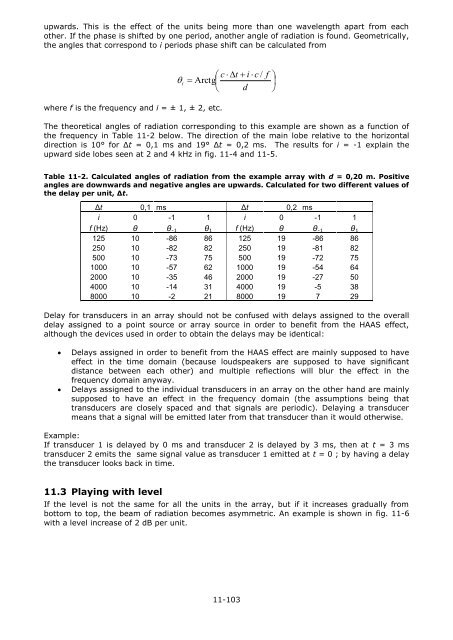
upwards. This is the effect of the units being more than one wavelength apart from each<br />
other. If the phase is shifted by one period, another angle of radiation is found. Geometrically,<br />
the angles that correspond to i periods phase shift can be calculated from<br />
c t<br />
i c /<br />
i<br />
Arctg<br />
d<br />
f<br />
<br />
<br />
<br />
where f is the frequency and i = ± 1, ± 2, etc.<br />
The theoretical angles of radiation corresponding to this example are shown as a function of<br />
the frequency in Table 11-2 below. The direction of the main lobe relative to the horizontal<br />
direction is 10° for Δt = 0,1 ms and 19° Δt = 0,2 ms. The results for i = -1 explain the<br />
upward side lobes seen at 2 and 4 kHz in fig. 11-4 and 11-5.<br />
Table 11-2. Calculated angles of radiation from the example array with d = 0,20 m. Positive<br />
angles are downwards and negative angles are upwards. Calculated for two different values of<br />
the delay per unit, Δt.<br />
Δt 0,1 ms Δt 0,2 ms<br />
i 0 -1 1 i 0 -1 1<br />
f (Hz) θ θ -1 θ 1 f (Hz) θ θ -1 θ 1<br />
125 10 -86 86 125 19 -86 86<br />
250 10 -82 82 250 19 -81 82<br />
500 10 -73 75 500 19 -72 75<br />
1000 10 -57 62 1000 19 -54 64<br />
2000 10 -35 46 2000 19 -27 50<br />
4000 10 -14 31 4000 19 -5 38<br />
8000 10 -2 21 8000 19 7 29<br />
Delay for transducers in an array should not be confused with delays assigned to the overall<br />
delay assigned to a point source or array source in order to benefit from the HAAS effect,<br />
although the devices used in order to obtain the delays may be identical:<br />
<br />
<br />
Delays assigned in order to benefit from the HAAS effect are mainly supposed to have<br />
effect in the time domain (because loudspeakers are supposed to have significant<br />
distance between each other) and multiple reflections will blur the effect in the<br />
frequency domain anyway.<br />
Delays assigned to the individual transducers in an array on the other hand are mainly<br />
supposed to have an effect in the frequency domain (the assumptions being that<br />
transducers are closely spaced and that signals are periodic). Delaying a transducer<br />
means that a signal will be emitted later from that transducer than it would otherwise.<br />
Example:<br />
If transducer 1 is delayed by 0 ms and transducer 2 is delayed by 3 ms, then at t = 3 ms<br />
transducer 2 emits the same signal value as transducer 1 emitted at t = 0 ; by having a delay<br />
the transducer looks back in time.<br />
11.3 Playing with level<br />
If the level is not the same for all the units in the array, but if it increases gradually from<br />
bottom to top, the beam of radiation becomes asymmetric. An example is shown in fig. 11-6<br />
with a level increase of 2 dB per unit.<br />
11-103


