Download - Odeon
Download - Odeon
Download - Odeon

You also want an ePaper? Increase the reach of your titles
YUMPU automatically turns print PDFs into web optimized ePapers that Google loves.
oom; such as windows, doors, paintings, blackboards etc. one should however not expect<br />
these elements to provide effective scattering down to infinitely low frequencies. From diffuser<br />
theory it is found that typical behaviour is that the effectiveness of a diffuser decreases rapidly<br />
below a cut-off frequency which can roughly be defined from the depth of the diffuser (wall<br />
construction) being less than half a wave length. Two octave bands below the cut-off<br />
frequency the diffuser is no longer effective. At the lowest frequencies however, the<br />
dimensions of the room will provide some diffraction, therefore the dimensions of the<br />
reflecting panel as used in the formulae for f l and f w are substituted with the approximate<br />
dimensions of the room at the lowest frequencies and a combination of surface and room<br />
dimensions are used for frequencies in-between high and low frequencies. It is worth noticing<br />
that it is not only the depth of the wall construction which enables the elements of the wall<br />
construction to provide diffraction, also angling between the surfaces, offsets e.g. the door<br />
being mounted in a door hole or the surfaces being made of different materials provides the<br />
phase shifts which results in diffraction. Therefore it may be reasonable to assume that the<br />
boundary walls have a minimum depth of say 10 cm in order to account for such phase shifts.<br />
The typical depth of geometry’s wall construction should be specified in the Interior margin in the<br />
room setup. ODEON will use this number in order to distinguish between interior and boundary<br />
surfaces. Once the margin has been entered and the room setup dialog has been closed the<br />
3DView will display surfaces which are considered to be interior in a greenish colour while the<br />
exterior is displayed in black. Diffraction from the exterior will be calculated taking into<br />
account that diffraction is limited towards the lowest frequencies because of limited depth of<br />
the wall constructions.<br />
Limitations<br />
In special cases the Reflection Based Scattering Coefficient may overestimate the scattering<br />
provided by small surfaces which are only fractions of a bigger whole e.g. small surfaces being<br />
part of a curved wall or dome. Such surfaces should not cause diffraction due to their<br />
individual area because the individual surfaces do not provide any significant edge diffraction.<br />
In these cases the method can be bypassed by setting the surface Type to Fractional in the Materials<br />
List, see chapter 4. When setting the Type to Fractional, the surface area used for calculating the<br />
Reflection Based Scattering Coefficient is determined from the box subscribing the room rather<br />
than the individual surface - if the construction part which the fractional surface is part of, is<br />
considerable smaller that the 'room box' scattering might be underestimated and a higher<br />
scattering coefficient should be assigned to the surface.<br />
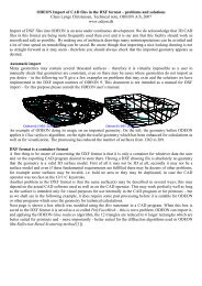
d diffuser<br />
Figure 6-5. A typical diffuser depth (interior margin) entered by user determines which<br />
parts of the geometry should be considered exterior of a room, thus limiting the scattering<br />
of the boundary surfaces which can not be considered freely suspended at the lowest<br />
frequencies.<br />
6.5 Oblique Lambert<br />
In the ray-tracing process, a number if secondary sources are generated at the collision points<br />
between walls and the rays traced. It has not been covered yet which directivity to assign to<br />
these sources. A straight away solution which is the one ODEON has been applying until<br />
version 8 is to assign Lambert directivity patterns, that is, the cosine directivity which is a<br />
model for diffuse area radiation. However the result would be that the last reflection from the<br />
secondary sources to the actual receiver point is handled with 100% scattering, no matter<br />
actual scattering properties for the reflection. This is not the optimum solution, in fact when it<br />
comes to the last reflection path from wall to receiver we know not only the incident path<br />
length to the wall also the path length from the wall to the receiver is available, allowing a<br />
better estimate of the characteristic distance a* than was the case in the ray-tracing process<br />
where d refl was assumed to be equal to d inc . So which directivity to assign to the secondary<br />
sources? We propose a directivity pattern which we will call Oblique Lambert. Reusing the<br />
6-76