CPC Peripherals Installation and Operation - Emerson Climate ...
CPC Peripherals Installation and Operation - Emerson Climate ...
CPC Peripherals Installation and Operation - Emerson Climate ...

Create successful ePaper yourself
Turn your PDF publications into a flip-book with our unique Google optimized e-Paper software.
Indoor Relative Humidity Sensor (P/N 203-5750)<br />
Overview<br />
The indoor relative humidity sensor uses a capacitorbased<br />
humidity sensor for measurement of relative humidity.<br />
The indoor humidity sensor (P/N 203-5750) comes<br />
with an enclosure designed to be mounted on a wall.<br />
The sensing element for indoor humidity sensor is a<br />
General Eastern bulk resistance type sensor. Table 4 lists<br />
the sensor’s specifications:<br />
Operating<br />
Specifications<br />
10% to 99% RH (noncondensing)<br />
Range -40° to 170° F (-40 to 76° C)<br />
Storage Tem- -85° to 158° F<br />
perature (-65° to 70° C)<br />
Hysteresis Less than 1% RH<br />
Supply Voltage<br />
9.5 to 36 VDC<br />
Signal Outputs<br />
0 to 5 volts (0 to 100% RH linear)<br />
Accuracy<br />
Range<br />
±3%<br />
Table 4 - RH Sensor Specifications<br />
<strong>Installation</strong><br />
Mounting the Indoor RH Sensor<br />
The indoor relative humidity sensor should be mounted<br />
in a central location within the zone to be measured, away<br />
from doors, windows, vents, heaters, <strong>and</strong> outside walls that<br />
could affect temperature readings. The sensor should be between<br />
four <strong>and</strong> six feet from the floor.<br />
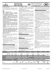
Mount the sensor as follows:<br />
1. Remove the two screws from the sides of the<br />
enclosure, <strong>and</strong> remove the cover.<br />
2. Mount the sensor to the wall using the two<br />
mounting holes near the flattened corners of<br />
the mounting plate (as shown in Figure 19).<br />
3. Replace the cover <strong>and</strong> the cover mounting<br />
screws.<br />
�������<br />
��������<br />
Figure 19 - Indoor RH Mounting Dimensions<br />
Wiring<br />
������<br />
��������<br />
������<br />
��������<br />
INDOOR MOUNTING DIMENSIONS<br />
26509025<br />
Wire the relative humidity sensor to an input board as<br />
shown in Figure 20.<br />
1. Wire the terminal labelled “P” to one of the<br />
12V supply terminals on the input board<br />
(POWER).<br />
2. Wire the terminal labelled “GND” to the oddnumbered<br />
terminal of an input board point<br />
(GND).<br />
3. Wire the terminal labelled “OUT” to the<br />
even-numbered terminal of an input board<br />
point (SIG).<br />
4. Jumper the terminal labelled “N” to the<br />
“GND” terminal.<br />
<strong>Peripherals</strong> Manual Indoor Relative Humidity Sensor (P/N 203-5750) • 23