CPC Peripherals Installation and Operation - Emerson Climate ...
CPC Peripherals Installation and Operation - Emerson Climate ...
CPC Peripherals Installation and Operation - Emerson Climate ...

Create successful ePaper yourself
Turn your PDF publications into a flip-book with our unique Google optimized e-Paper software.
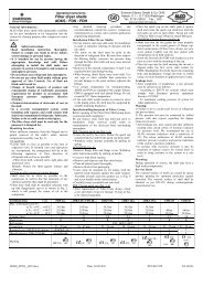
5. Cut off the shield at the transducer <strong>and</strong><br />
ground at either a ground lug or an odd terminal<br />
on the 16AI board.<br />
6. Set the corresponding 16AI Input Type Dip<br />
Switch to the DOWN position, as shown in<br />
Figure 24.<br />
Figure 24 - Single Refrigerant Transducer Layout<br />
Multiple Refrigerant Transducers Layout<br />
A maximum of sixteen RTs may be connected to one<br />
power supply.<br />
Do NOT jumper the -V <strong>and</strong> 0V terminals of the refrigerant<br />
transducer.<br />
Connect the refrigerant transducers to the 16AI input<br />
board <strong>and</strong> power supply as shown in Figure 25.<br />
1. Attach the black wire to the -V terminal of<br />
each of the RTs <strong>and</strong> the 0V terminal to the<br />
power supply.<br />
2. Attach the green wire to the 0V terminal of<br />
each of the RTs <strong>and</strong> an odd terminal on the<br />
16AI input connections.<br />
<strong>Peripherals</strong> Manual Refrigerant Transducer (P/N 809-1550) • 29