CPC Peripherals Installation and Operation - Emerson Climate ...
CPC Peripherals Installation and Operation - Emerson Climate ...
CPC Peripherals Installation and Operation - Emerson Climate ...

Create successful ePaper yourself
Turn your PDF publications into a flip-book with our unique Google optimized e-Paper software.
Refrigerant Transducer (P/N 809-1550)<br />
Overview<br />
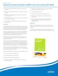
The Refrigerant Transducer (RT) (P/N 809-1550),<br />
shown in Figure 23, monitors a specified area for the presence<br />
of refrigerant. When refrigerant is detected, the RT<br />
sends a signal to a 16AI input board, <strong>and</strong> to a <strong>CPC</strong> controller<br />
such as the Building Environmental Control (BEC) or<br />
Refrigeration Monitor <strong>and</strong> Case Control (RMCC). The<br />
16AI input board is capable of supporting up to sixteen<br />
RTs, although an additional power supply is required if<br />
more than one RT is connected to a 16AI board. The clearing<br />
cycle, warm-up cycle, <strong>and</strong> temperature compensation<br />
are unique <strong>CPC</strong> RT features that reduce false leak signals<br />
<strong>and</strong> improve leak detection capabilities. The transducer is<br />
enclosed in a protective case to prevent damage to the refrigerant<br />
sensor.<br />
Figure 23 - Refrigerant Transducer (Sensor Removed)<br />
Refrigerant Transducer Sensor Type<br />
The refrigerant transducer is supplied with either of two<br />
sensors depending on the refrigerant to be detected. Table<br />
6 shows the refrigerant type <strong>and</strong> the sensor part number that<br />
should be used.<br />
Product Number 209-0830 209-0832<br />
Heater Voltage 5.0 V ± 0.2 V (AC or DC)<br />
Circuit Voltage Max. 24 V (AC or DC, PS ≤ 15<br />
mW)<br />
Load Resistance Variable (PS ≤ 15 mW)<br />
Sensor 1 kΩ ~ 5 kΩ for 4 kΩ ~ 40 kΩ<br />
Resistance<br />
R-22 at 1000<br />
ppm/Air<br />
for R-134a at<br />
100 ppm/Air<br />
Change Ratio of<br />
Sensor<br />
Resistance<br />
Features<br />
• Can be used with long cable runs<br />
• Compact design<br />
• Low power consumption<br />
• Clearing Cycle eliminates effects of prior refrigerant<br />
exposure<br />
• Warm-up Cycle prevents false signals during initial<br />
power-up<br />
• Temperature Compensation reduces false signals<br />
during large temperature change conditions<br />
• No calibration adjustments required<br />
<strong>Installation</strong><br />
Power<br />
0.30 ± 0.10<br />
(Rs/Ro)<br />
0.50 ~ 0.65<br />
(Rs/Ro)<br />
Heater Resistance 30.0 Ω ± 3.0 Ω at Room Temperature<br />
Heater Power VH=5.0 V (835 ± 90 mW)<br />
Consumption<br />
High Sensitivity<br />
To<br />
R-113, R-22,<br />
R-12, R-11<br />
R134a, R-22,<br />
R-12<br />
Table 6 - Refrigerant Transducer Sensor Part Numbers<br />
RTs require special power considerations during power-up.<br />
Do not substitute other power supplies for <strong>CPC</strong><br />
Power Supply (P/N 258-1000).<br />
If only one RT is to be used per 16AI board, then the RT<br />
may be powered directly by the 16AI power output connec-<br />
<strong>Peripherals</strong> Manual Refrigerant Transducer (P/N 809-1550) • 27