

SPORE Mission Design - Georgia Tech SSDL - Georgia Institute of ...
SPORE Mission Design - Georgia Tech SSDL - Georgia Institute of ...
SPORE Mission Design - Georgia Tech SSDL - Georgia Institute of ...

You also want an ePaper? Increase the reach of your titles
YUMPU automatically turns print PDFs into web optimized ePapers that Google loves.
this center <strong>of</strong> gravity requirement cannot be met for the 1U and 2x2U vehicles. A 6DOF model <strong>of</strong> the<br />
<strong>SPORE</strong> entry trajectory was created using POSTII to assess dynamic stability during the hypersonic,<br />
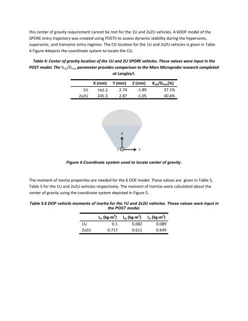
supersonic, and transonic entry regimes. The CG location for the 1U and 2x2U vehicles is given in Table<br />
4.Figure 4depicts the coordinate system to locate the CG.<br />
Table 4: Center <strong>of</strong> gravity location <strong>of</strong> the 1U and 2U <strong>SPORE</strong> vehicles. These values were input in the<br />
POST model. The X CG /D max parameter provides comparison to the Mars Microprobe research completed<br />
at Langley9.<br />
X (mm) Y (mm) Z (mm) X CG /D max (%)<br />
1U 143.3 2.74 -1.89 37.1%<br />
2x2U 245.3 2.87 -1.05 40.6%<br />
Figure 4.Coordinate system used to locate center <strong>of</strong> gravity.<br />
The moment <strong>of</strong> inertia properties are needed for the 6 DOF model. These values are given in Table 5,<br />
Table 5 for the 1U and 2x2U vehicles respectively. The moment <strong>of</strong> inertias were calculated about the<br />
center <strong>of</strong> gravity using the coordinate system depicted in Figure 5.<br />
Table 5.6 DOF vehicle moments <strong>of</strong> inertia for the 1U and 2x2U vehicles. These values were input in<br />
the POST model.<br />
I xx (kg-m 2 ) I yy (kg-m 2 ) I zz (kg-m 2 )<br />
1U 0.1 0.082 0.089<br />
2x2U 0.717 0.611 0.649


