

SPORE Mission Design - Georgia Tech SSDL - Georgia Institute of ...
SPORE Mission Design - Georgia Tech SSDL - Georgia Institute of ...
SPORE Mission Design - Georgia Tech SSDL - Georgia Institute of ...

Create successful ePaper yourself
Turn your PDF publications into a flip-book with our unique Google optimized e-Paper software.
4.8 Parachute Selection<br />
To keep the payload intact, the 1U vehicle must touchdown with an impact velocity below 5 m/s. The 1U<br />
vehicle uses a cross parachute manufactured by Pioneer Aerospace for use on 16 kg flares. The<br />
parachute is capable <strong>of</strong> meeting the 5 m/s requirement for vehicles less than 18 kg. A mortar for this<br />
parachute consists <strong>of</strong> a gas generator with electrical ignition, which will push up a sabot and eject the<br />
packaged parachute from the top <strong>of</strong> the backshell. A backshell cap, held in place by shear pins, will pop<br />
<strong>of</strong>f when pressure becomes too great and release the parachute. The specifications fpr the 1U<br />
parachute are provided in Table 16.<br />
Table 16.1U parachute specifications.<br />
Parachute type C D A (m 2 ) D 0 (m) Mass (kg)<br />
Cross 0.66 15.904 4.5 1.06<br />
To ensure survival <strong>of</strong> the biological and material science payloads, the 2x2U vehicle must not exceed<br />
40g’s during impact and parachute deployment. Discussions with Pioneer Aerospace are currently<br />
underway to find a parachute and mortar system that meets the 2x2U requirements, but a preliminary<br />
parachute model was developed to ensure all the entry requirements are met.<br />
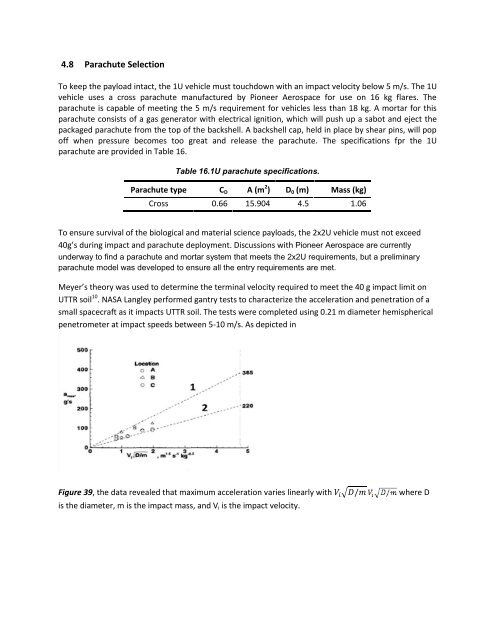
Meyer’s theory was used to determine the terminal velocity required to meet the 40 g impact limit on<br />
UTTR soil 10 . NASA Langley performed gantry tests to characterize the acceleration and penetration <strong>of</strong> a<br />
small spacecraft as it impacts UTTR soil. The tests were completed using 0.21 m diameter hemispherical<br />
penetrometer at impact speeds between 5-10 m/s. As depicted in<br />
Figure 39, the data revealed that maximum acceleration varies linearly with √ where D<br />
is the diameter, m is the impact mass, and V i is the impact velocity.


