SPORE Mission Design - Georgia Tech SSDL - Georgia Institute of ...
SPORE Mission Design - Georgia Tech SSDL - Georgia Institute of ...
SPORE Mission Design - Georgia Tech SSDL - Georgia Institute of ...
Create successful ePaper yourself
Turn your PDF publications into a flip-book with our unique Google optimized e-Paper software.
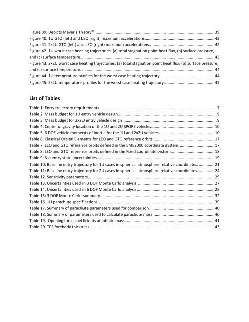
Figure 39: Depicts Meyer’s Theory 16 . .......................................................................................................... 39<br />
Figure 40. 1U GTO (left) and LEO (right) maximum accelerations. ............................................................. 42<br />
Figure 41. 2x2U GTO (left) and LEO (right) maximum accelerations.. ........................................................ 42<br />
Figure 42. 1U worst case heating trajectories: (a) total stagnation point heat flux, (b) surface pressure,<br />
and (c) surface temperature. ...................................................................................................................... 43<br />
Figure 43. 2x2U worst case heating trajectories: (a) total stagnation point heat flux, (b) surface pressure,<br />
and (c) surface temperature. ...................................................................................................................... 44<br />
Figure 44. 1U temperature pr<strong>of</strong>iles for the worst case heating trajectory. ............................................... 44<br />
Figure 45. 2x2U temperature pr<strong>of</strong>iles for the worst case heating trajectory............................................. 45<br />
List <strong>of</strong> Tables<br />
Table 1: Entry trajectory requirements. ....................................................................................................... 7<br />
Table 2. Mass budget for 1U entry vehicle design. ....................................................................................... 9<br />
Table 3. Mass budget for 2x2U entry vehicle design .................................................................................... 9<br />
Table 4: Center <strong>of</strong> gravity location <strong>of</strong> the 1U and 2U <strong>SPORE</strong> vehicles.. ...................................................... 10<br />
Table 5. 6 DOF vehicle moments <strong>of</strong> inertia for the 1U and 2x2U vehicles. ................................................ 10<br />
Table 6: Classical Orbital Elements for LEO and GTO reference orbits....................................................... 17<br />
Table 7: LEO and GTO reference orbits defined in the EME2000 coordinate system. ............................... 17<br />
Table 8: LEO and GTO reference orbits defined in the Fixed coordinate system. ...................................... 18<br />
Table 9: 3-σ entry state uncertainties ......................................................................................................... 19<br />
Table 10: Baseline entry trajectory for 1U cases in spherical atmosphere relative coordinates. .............. 21<br />
Table 11: Baseline entry trajectory for 2U cases in spherical atmosphere relative coordinates. .............. 24<br />
Table 12. Sensitivity parameters ................................................................................................................. 29<br />
Table 13. Uncertainties used in 3 DOF Monte Carlo analysis. .................................................................... 27<br />
Table 14. Uncertainties used in 6 DOF Monte Carlo analysis ..................................................................... 28<br />
Table 15: 3 DOF Monte Carlo summary ...................................................................................................... 32<br />
Table 16. 1U parachute specifications. ....................................................................................................... 39<br />
Table 17. Summary <strong>of</strong> parachute parameters used for comparison .......................................................... 40<br />
Table 18. Summary <strong>of</strong> parameters used to calculate parachute mass.. ..................................................... 40<br />
Table 19. Opening force coefficients at infinite mass. ............................................................................... 41<br />
Table 20. TPS forebody thickness. .............................................................................................................. 43


